Dimensional tolerances, ISO fits and surface roughness
Deviations and tolerance, IT grades and position letters, clearance, transition and interference fits with numerical examples, hole basis, general tolerances and Ra roughness.
No part is made to the exact size: a 20 mm shaft will leave the lathe at 19.993 or 20.008 mm. The designer has to state how far machining may stray without spoiling the function. This is the tolerance. Make it too tight and costs rise; too loose and parts will not assemble or will move badly. The ISO system of limits and fits (ISO 286) solves the problem with a code of one letter and one number.
Terms
- Nominal size: the design size, for example 20 mm.
- Upper and lower deviation: how much the actual size may be larger or smaller than nominal. For a hole they are written ES and EI, for a shaft es and ei.
- Tolerance: the difference between the maximum and minimum size, that is the width of the permitted zone.
- Zero line: the line representing the nominal size in tolerance diagrams.
A dimension such as  means the hole can measure from 20.000 to 20.021 mm: a tolerance of 21 µm.
The ISO system: grade and position
Every ISO tolerance is written as a letter and a number, for example H7 or g6.
- The number is the standard tolerance grade (IT), from IT01 to IT18. It sets the width of the zone: the lower it is, the more precise the machining. The width also grows with nominal size, because precision is harder on large parts. For 20 mm, IT6 is 13 µm and IT7 is 21 µm.
- The letter sets the position of the zone relative to the zero line. Capitals for holes, lower case for shafts. H means a hole with zero lower deviation (it cannot be smaller than nominal); h a shaft with zero upper deviation.
Typical grades: IT5 to IT7 for grinding and precision turning, IT8 to IT11 for ordinary turning and milling, IT12 to IT16 for pressed or cut parts where precision does not matter.
Fits
When a shaft goes into a hole, their relationship depends on where the two tolerance zones lie.
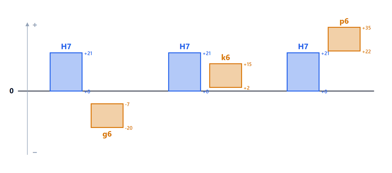
- Clearance fit: the shaft is always smaller than the hole. H7/g6: clearance between 7 µm (smallest hole, largest shaft) and 41 µm (largest hole, smallest shaft). For pins that must turn or slide.
- Transition fit: depending on the actual parts there may be a small clearance or a small interference. H7/k6: from 19 µm clearance to 15 µm interference. For parts that must be accurately located and removed with a puller or light blows, such as keyed pulleys or bearing inner rings.
- Interference fit: the shaft is always larger than the hole. H7/p6: interference from 1 to 35 µm. It is assembled with a press or by heating the outer part, and transmits torque by friction, without keys.
Computing clearance and interference

If the minimum clearance is negative there is interference. For H7/g6 at 20 mm: maximum clearance  µm, minimum clearance
 µm.
Hole basis and shaft basis
To reduce the number of tools and gauges a system is chosen:
- hole basis: all holes are H, and the fit is obtained by varying the shaft. It is the most common, because a shaft is easier to machine and measure than a hole, while holes need reamers and plug gauges specific to each tolerance;
- shaft basis: all shafts are h, and the hole varies. It is used when several parts with different fits are mounted on one long ground shaft.
On the drawing of a single part you write the part’s tolerance (⌀20 H7); on an assembly drawing the fit (⌀20 H7/g6).
General tolerances
Writing a tolerance on every dimension would be impossible. Dimensions without an explicit tolerance follow the general tolerances referenced in the title block, for example “ISO 2768-m”. Class m (medium) allows for example ±0.2 mm on sizes between 6 and 30 mm and ±0.3 mm between 30 and 120 mm. Specific tolerances are given only where they are really needed.
Surface roughness
Even a “smooth” surface has microscopic peaks and valleys. The most used parameter is Ra, the arithmetic mean deviation of the profile from its mean line, in micrometres. It is shown with a check-mark-like symbol with the value next to it (ISO 21920-1, which replaced ISO 1302).
| Ra (µm) | Typical process |
|---|---|
| 12.5 – 25 | roughing, sawing |
| 3.2 – 6.3 | ordinary turning and milling |
| 0.8 – 1.6 | fine turning, mating surfaces |
| 0.1 – 0.4 | grinding, lapping, sealing surfaces |
Tolerance and roughness go together: there is no point asking for an IT6 tolerance on a surface with Ra 12.5, because the peaks would be taller than the tolerance itself.




