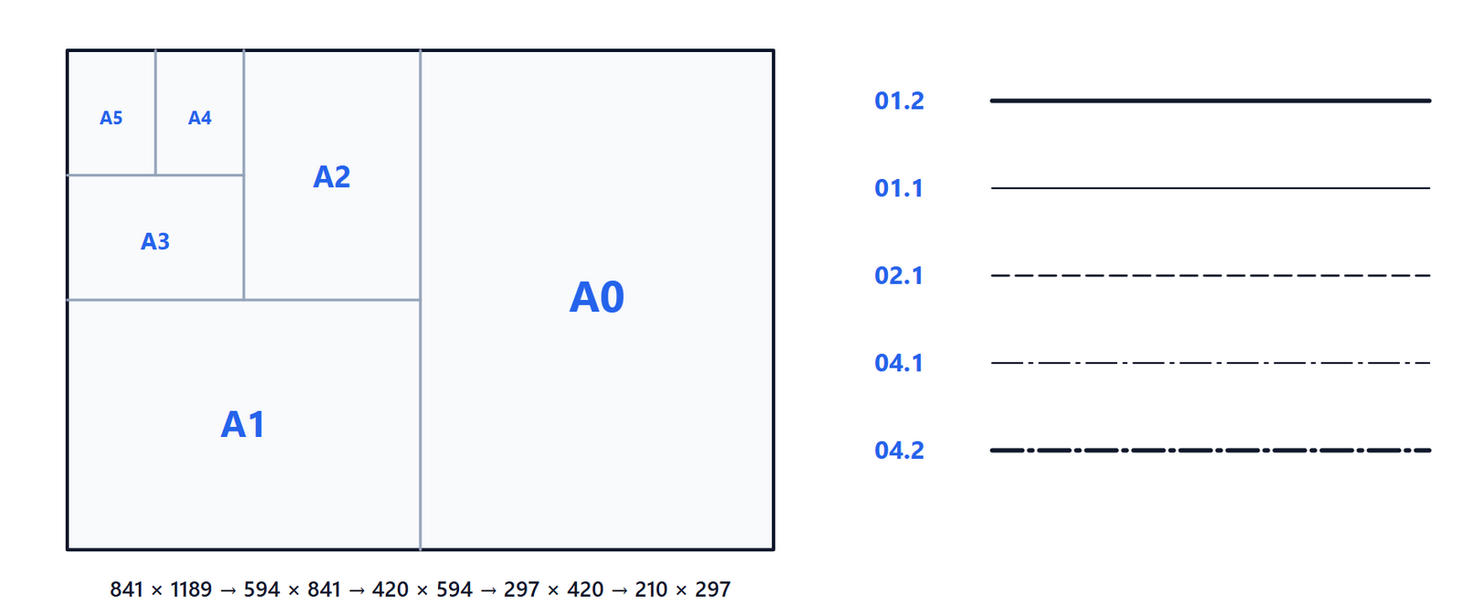
Sections and hatching in technical drawing
The principle of sectioning, how the cutting plane is marked, hatching rules, features that are not sectioned, full, half, local, offset, revolved and removed sections.
A part with holes, cavities and counterbores, drawn only with orthographic views, fills up with overlapping dashed lines and becomes unreadable. The solution is to cut it with an imaginary plane and show what is inside: the section. The rules are in ISO 128-40 and 128-50.
The principle
Imagine cutting the part with a plane, removing the piece between the observer and the plane, and drawing what is left using orthographic projection. The surfaces cut by the plane are hatched; edges seen behind the plane are drawn normally with a wide line. Hidden lines are normally no longer drawn in sections: getting rid of them is the whole point.
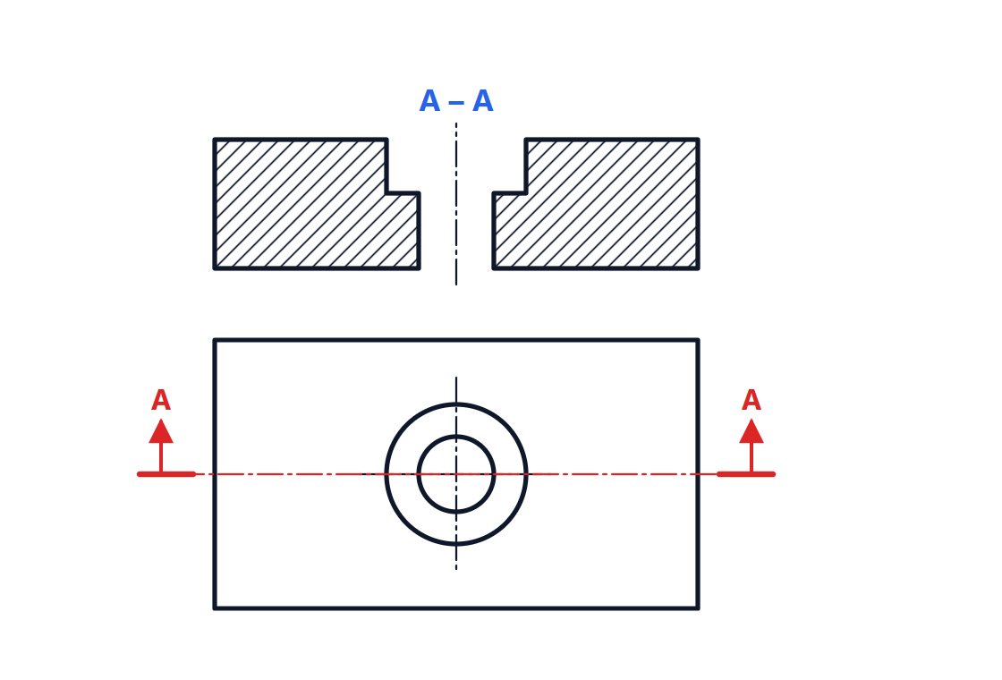
How a section is marked
- The trace of the cutting plane is drawn on another view with the narrow chain line, made wide at the ends and wherever it changes direction.
- At the ends there are two arrows showing the viewing direction, and two identical capital letters.
- Above the section its name is written, for example A-A.
If the cutting plane coincides with a plane of symmetry of the part and the position of the section is obvious, the marking may be omitted.
Hatching
- Continuous narrow parallel lines, inclined at 45° to the main outline or to the axes of symmetry.
- The spacing suits the size of the area, but for the same part it must be the same in every section.
- Different parts in contact in an assembly are hatched with different angles or spacing, so they can be told apart.
- Very thin areas (gaskets, sheet metal) can be filled in solid.
- Dimensions and text interrupt the hatching, not the other way round.
Standards also provide special hatchings to indicate materials, but in mechanical drawing the generic hatching is almost always used and the material is written in the title block.
What is not sectioned
Some features, when cut by a plane through their axis, are not hatched and are drawn as if whole, because sectioning would add no information and would make the drawing confusing:
- shafts, pins, dowels, keys;
- screws, bolts, nuts, washers, rivets;
- balls and rollers of bearings;
- ribs and wheel spokes, when the plane cuts them lengthwise.
A screw in a threaded hole, in a sectioned assembly, appears whole inside the hatched part.
Types of section
- Full section: the plane goes right through the part, as in the figure.
- Half section: for symmetrical parts only half is sectioned and the other half is drawn as a view. A single figure then shows both outside and inside; the two halves are separated by the axis of symmetry (narrow chain line), not by a wide line.
- Local (broken-out) section: only a small area is “broken out”, bounded by a freehand narrow line, to show a detail such as a blind hole.
- Offset (stepped) section: the cutting plane steps to pass through several features, for example holes that are not in line. The steps are marked on the trace with wide strokes, but they are not drawn in the section.
- Revolved section: the cross-section of a bar or arm is rotated by 90° and drawn on top of the view itself, with a narrow outline.
- Removed section: the same, drawn next to the view with a wide outline and linked to the cutting plane. It is the usual way to show the profile of a shaft with a keyway.
An example: the plate with a counterbored hole
The plate in the figure has a 14 mm through hole with a 26 mm counterbore 10 mm deep, that is a widening in which a screw head sits flush. The top view alone shows two concentric circles, but it does not say which one is on top nor how deep the counterbore is. The front view without a section would need six dashed lines. Section A-A settles everything: the profile of the hole, with its step, can be read at a glance and dimensioned directly.
Sections in assembly drawings
In assembly drawings sections are essential: they show how the parts fit together, where seals work, how a bearing is mounted. For an electronics engineer they are useful for enclosures too: a section shows how the board is fixed to its standoffs, where a connector passes through the panel and how much room is left above the tallest components.