Orthographic projection: first and third angle, views and hidden lines
The principle of projection, first and third angle methods and their symbol, correspondence between views, hidden lines, how to read a drawing and special views.
An object has three dimensions, the sheet has two. Orthographic projection solves the problem by showing the part with several flat views, each one seen “from very far away” along a direction perpendicular to the sheet. No view is enough on its own, but together they describe the part unambiguously and, unlike a photograph, they keep the true dimensions. It is the heart of technical drawing.
The principle
Imagine the part inside a transparent cube. From each face of the cube you look at it with lines of sight that are parallel to each other and perpendicular to that face, and you draw what you see. Since the lines of sight are parallel, edges parallel to the projection plane appear in true length: a 60 mm side measures 60 mm (to scale) on the drawing. Inclined edges appear shortened, and edges perpendicular to the plane shrink to a point.
There are six principal views (front, top, bottom, left, right, rear), but two or three are usually enough. The front view (or principal view) is chosen to show the most characteristic shape of the part, with as few hidden lines as possible, in its machining or working position.
First-angle (E) and third-angle (A) projection
The views are arranged on the sheet around the front view according to fixed rules (ISO 128-30, formerly ISO 5456-2).
- First-angle projection (method E), used in Italy and Europe: the object sits between the observer and the projection plane. The top view goes below the front view, the view from the left goes on the right, the view from the right on the left.
- Third-angle projection (method A), used in the United States: the projection plane sits between the observer and the object. The top view goes above, the view from the left on the left.
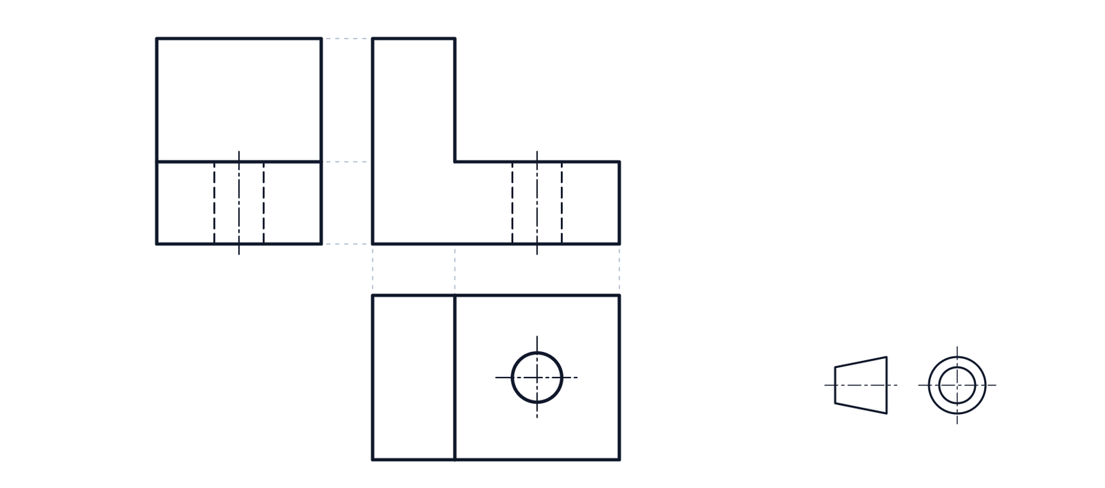
With the same views, the two methods put them in opposite positions. That is why the title block always shows the projection symbol: a truncated cone seen from the side and from the end. In first angle the two circles are to the right of the trapezium; in third angle, to the left. Reading an American drawing as if it were first angle means making a mirrored part.
Correspondence between views
The views are not independent: they are “aligned”.
- Front view and top view have the same width and are aligned vertically.
- Front view and side views have the same height and are aligned horizontally.
- Top view and side views have the same depth.
The thin projection lines in the figure show these correspondences. They are the method for building a missing view from the other two, and for checking a drawing: every edge must have a match in the other views.
Visible and hidden lines
Visible edges are drawn with the continuous wide line, hidden ones with the dashed narrow line. In the figure the hole cannot be seen in the front or side views, because it is inside the material: it appears as two dashed lines, its sides, and a chain line, its axis. In the top view it is seen directly: a circle with two crossing centre lines.
Hidden lines should be used with judgement: if they help to understand the shape they should be drawn; if they clutter the drawing, a section is better (see the lesson on sections).
How to read a drawing
Reading projections is a skill that takes practice. A practical method:
- look at the view that says most (usually the front view) and pick out the main shapes;
- for each area of the front view, find the matching area in the other views using the projection lines;
- ask, for each line: is it an edge, the outline of a curved surface, or the intersection of two surfaces?
- imagine the part in 3D and check that it really produces all the views.
Example. In the figure, the front view alone could be an L-shaped part of any depth, or even a bent sheet. The top view says it is 40 mm deep and solid, the vertical line inside it shows where the height changes, and the circle reveals the hole, which in the other views is only dashed. The side view shows the step between base and upright.
Special views
- Partial views: when part of a view is enough, it is broken off with a freehand or zigzag narrow line.
- Auxiliary views: for an inclined face, project onto a plane parallel to that face, so it appears in true size.
- Symmetrical parts: half a view can be drawn, marking the axis of symmetry with two short parallel strokes at each end.
- Enlarged details: a small area is circled, identified with a letter and redrawn separately at a larger scale.