Technical drawing: standards, sheet sizes, scales and line types
The A-series sizes and why their ratio is the square root of 2, border and title block, standard scales, ISO 128 line types and lettering.
A technical drawing is a document, not an illustration: it must allow anyone, in any country, to make the part exactly as the designer intended. That is why it is governed by international standards (ISO, adopted in Italy as UNI EN ISO) that set sheet sizes, scales, line types and lettering. In this first lesson we look at these basic rules, which apply to the rest of the course.
The A-series sheet sizes
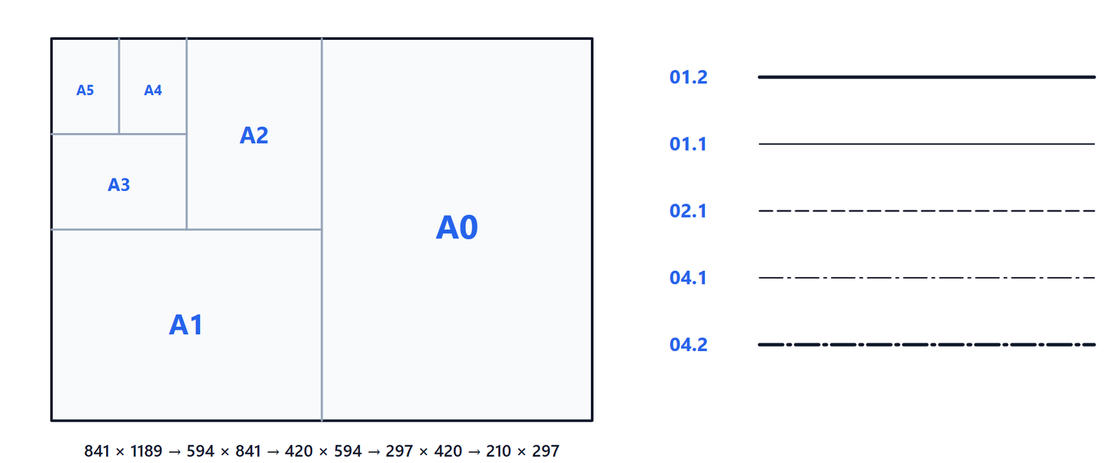
Drawing sheets follow the A series of ISO 216. Size A0 has an area of 1 m² and sides of 841 × 1189 mm; each following size is obtained by halving the long side of the previous one.
| Size | Dimensions (mm) |
|---|---|
| A0 | 841 × 1189 |
| A1 | 594 × 841 |
| A2 | 420 × 594 |
| A3 | 297 × 420 |
| A4 | 210 × 297 |
The ratio of the sides is always  , and that is exactly what lets you halve a sheet while keeping its proportions: if the sides are
 and
 , the two halves have sides
 and , with the same ratio. For the same reason a photocopy from A3 to A4 is a 71% reduction, that is
 .
Border and title block
The drawing does not reach the edge of the sheet. The border (ISO 5457) is a frame drawn with a wide line, 20 mm from the left edge, where the sheets are bound, and 10 mm from the others. At the bottom right sits the title block (ISO 7200), at most 180 mm wide. It contains:
- the title of the drawing and its identification number;
- the owner (company or school) and the names of who drew and who approved it;
- the date, the main scale and the projection method symbol;
- the sheet size, the sheet number and the revision index.
Drawings are always folded so that the title block stays visible on the front, in A4 size.
Scales
A part can rarely be drawn full size. The scale is the ratio between the size on the drawing and the real size, and ISO 5455 lists the recommended values:
- reduction: 1:2, 1:5, 1:10, 1:20, 1:50, 1:100, 1:200 and so on;
- full size: 1:1;
- enlargement: 2:1, 5:1, 10:1, 20:1, 50:1.
An 8 mm long screw drawn at 5:1 takes up 40 mm on the sheet. An important detail: dimensions always show the real size, whatever the scale. If the drawing is at 1:2 and the part is 100 mm wide, the line is 50 mm long but the number written is 100.
Line types
Every line has a precise meaning (ISO 128). Line widths follow a series in steps of (0.25, 0.35, 0.5, 0.7, 1 mm…), and a drawing normally uses two widths in a 2:1 ratio, for example 0.5 mm for wide lines and 0.25 mm for narrow ones.
| Line | Code | Use |
|---|---|---|
| continuous wide | 01.2 | visible edges and outlines |
| continuous narrow | 01.1 | dimension and extension lines, hatching, leader lines, outlines of revolved sections |
| dashed narrow | 02.1 | hidden edges and outlines |
| long-dashed dotted narrow | 04.1 | centre lines, axes of holes, pitch circles |
| long-dashed dotted wide | 04.2 | surfaces with special requirements |
The trace of a cutting plane is drawn with the narrow chain line, made wide at the ends and at changes of direction.
When two lines overlap there is a hierarchy: a visible edge covers a hidden one, a hidden edge covers a centre line.
Lettering
Lettering follows ISO 3098: simple stick characters, upright or slanted at 15°, with heights in the same series (2.5, 3.5, 5, 7 mm). CAD uses fonts that reproduce these characters (for example ISOCP in AutoCAD). Dimensions are usually written 3.5 mm high, titles 5 or 7 mm.
Why all these rules
A technical drawing goes to the workshop, is attached to a contract, ends up in an archive for decades. Every ambiguity costs something: a wrong part, a dispute with a supplier, a delay. Standards are the shared language that removes ambiguity. The same applies to an electronics engineer: an enclosure for a board, a heat sink or the drilling of a front panel are communicated to the machine shop precisely with a standard drawing.