Network architecture: layers, packet switching and delays
The Internet and OSI layered models, encapsulation, circuit and packet switching, the components of delay, the advantage of packet transmission proved, the bandwidth-delay product.
A telecommunication network must deliver data among billions of different devices, through cables, fibres and radio links of very different nature, run by different organisations. It succeeds by dividing the problem into layers, each with a precise task. In this lesson we look at the layered architecture and encapsulation, circuit and packet switching, the four components of delay, the proof of the advantage of packet transmission over a chain of nodes, and the bandwidth-delay product.
The layers
The Internet model has five layers:
- application: the programs that use the network (web, mail, video), with their protocols (HTTP, SMTP, DNS);
- transport: communication between two processes on two machines, reliable (TCP) or not (UDP);
- network: routing packets from source to destination across many nodes (IP);
- link: transfer over a single hop between two adjacent nodes (Ethernet, Wi-Fi);
- physical: bits on the medium, with the modulations and codes seen in Electrical Communications.
The OSI model has seven, adding presentation and session, which in the Internet are tasks of the applications. Each layer uses the services of the one below and offers services to the one above, and talks to the layer at the same level on the other side through a protocol: a set of rules on the format of messages and on the actions to take.
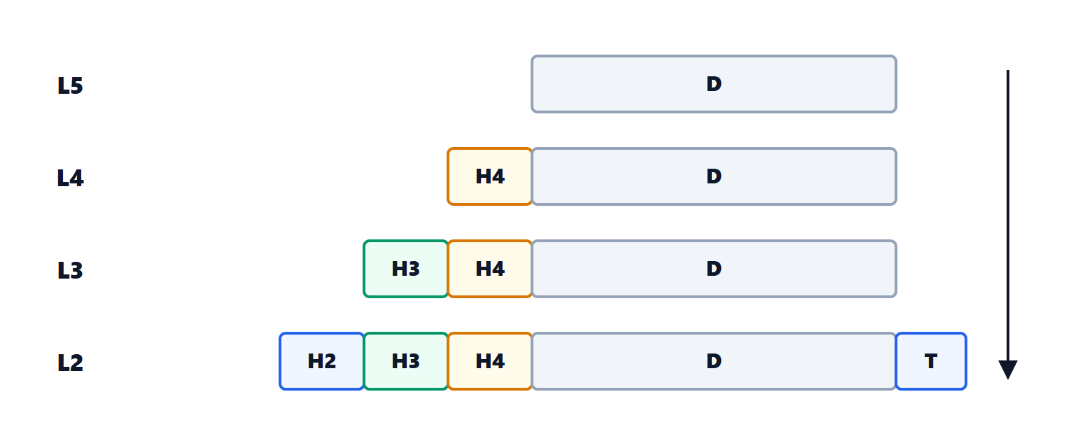
Going down, each layer adds its own header with the information its peer needs: ports for transport, IP addresses for the network, physical addresses and an error-check code (CRC, Electrical Communications lesson on codes) for the link. This is encapsulation. The advantage is modularity: Wi-Fi can be replaced by fibre without the browser noticing.
Circuits and packets
The traditional telephone network uses circuit switching: before talking, a path with fixed capacity is reserved for the whole duration of the call. Service is guaranteed, but the reserved capacity sits idle during silences. The Internet uses packet switching: data is divided into packets, each with the destination address, and each node forwards them one at a time, queuing them if the outgoing link is busy. Resources are shared among all users according to momentary demand (statistical multiplexing), with much more efficient use of capacity, at the price of variable delays and possible losses when queues fill up.
The components of delay
A packet of  bits crossing a node and the following link suffers four delays:
- processing: the node reads the header and decides where to forward it, microseconds;
- queuing: depends on traffic, from zero to many milliseconds (lesson on queues);
- transmission: the time to put all the bits onto the link of rate
 ,
 . A 1500-byte packet on a 100 Mb/s link takes 120 µs;
- propagation: the time a bit takes to cross the medium,
 , with
 about
 m/s in copper and fibre. For 1000 km it is 5 ms, whatever the link rate.
Why divide into packets
In store-and-forward nodes a packet must be received completely before it is retransmitted.
Theorem. A message divided into  packets of bits crosses
 links of rate (neglecting propagation, processing and queues) in a time
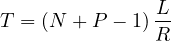
Proof. The first packet takes on each link and arrives after  . While the first crosses the second link, the second packet crosses the first link, and so on: the packets advance in line, and one arrives at the destination every . The last arrives
 after the first, i.e. at
 . ∎
Example. A 1 MB (8 Mbit) file over three 10 Mb/s links. As a single message ( ,
 Mbit) it takes
 s. Divided into 1000 packets of 8000 bits,
 s: a third. The longer the message relative to the number of hops, the closer packet transmission comes to the time of a single link. Moreover, an error forces retransmission of one packet rather than the whole message. The limit is the cost of headers, which weigh more on small packets.
The bandwidth-delay product
How many bits are “in flight” on the link at a given moment? The product of the rate and the propagation delay,  . With 1 Gb/s and 50 ms one way (an intercontinental route) it is 50 Mbit, more than 6 MB. The bandwidth-delay product, computed on the round-trip time (RTT), says how much data the sender must be able to send without waiting for acknowledgements in order to keep the link full: it is why TCP windows must be large on fast, distant networks (lesson on TCP).