Reinforced concrete: bending at the ultimate limit state
Concrete and steel with design strengths, assumptions and the stress block, the resisting moment proved with a complete example, yield check, ductility.
Concrete resists compression well and tension hardly at all; steel resists both but is expensive and, in slender elements, unstable. Reinforced concrete combines them: concrete carries compression, steel bars placed where the beam is in tension carry the tension. In this lesson we look at the materials with their design strengths, the ultimate limit state assumptions, the formula for the resisting moment of a rectangular section with its proof and a complete example, and ductility.
Materials
- Concrete: classified by its characteristic compressive strength on cylinders and cubes, for example C25/30 (
 MPa). The design strength is
 MPa, where 0.85 accounts for long-term loads. The tensile strength, about one tenth, is neglected in ultimate calculations.
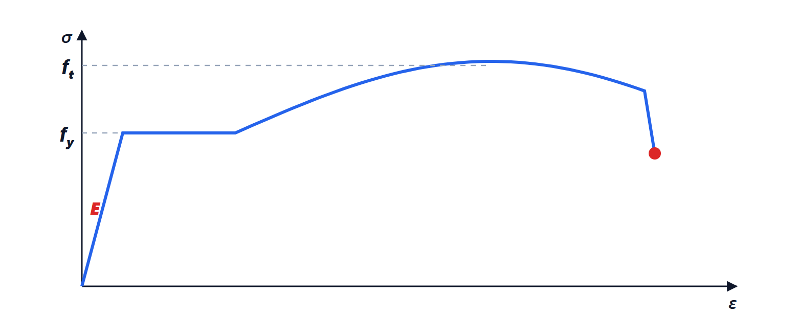
- Reinforcing steel B450C:
 MPa,
 MPa,
 GPa. The bars are ribbed to bond with the concrete.
The two materials work together because they bond, have almost the same coefficient of thermal expansion, and concrete, being alkaline, protects the steel from corrosion if the concrete cover is sufficient.
Ultimate limit state assumptions
- Sections remain plane (Structural Mechanics lesson on bending): strains vary linearly.
- Steel and concrete bond: the bar has the strain of the surrounding concrete.
- Concrete in tension does not work.
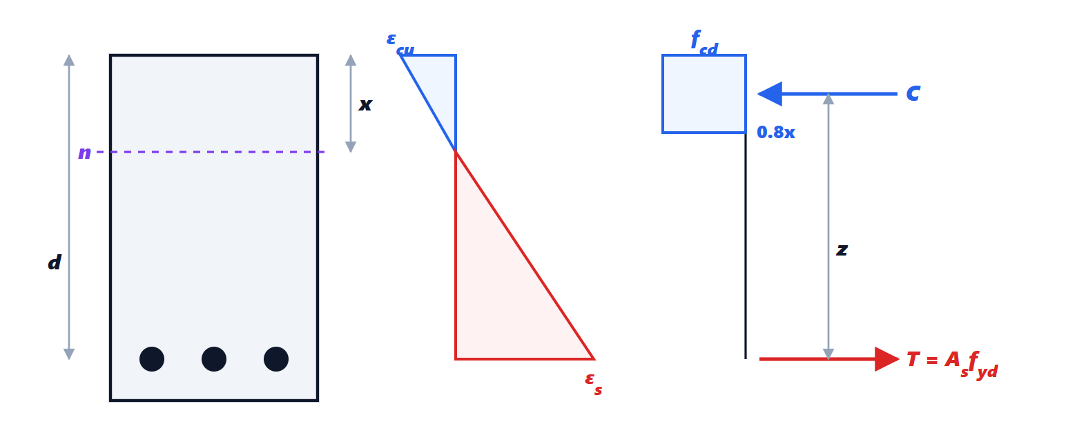
- Compressed concrete fails at strain
 %; its stress distribution, parabola-rectangle shaped, is replaced by a rectangular stress block of depth
 and stress
 , with
 the depth of the neutral axis.
The resisting moment
Theorem. For a rectangular section of width  and effective depth
 , with yielded tension reinforcement
 , the neutral axis depth and the resisting moment are

Proof. The stress block gives a compressive force  , applied at its centroid,
 from the compressed edge. The yielded steel gives a tension
 at depth . With no external axial force, translational equilibrium requires
 , hence . The two forces, equal and opposite, form a couple with lever arm
 : the resisting moment is
 . ∎
Example. A 300×500 mm beam, effective depth  mm, three 16 mm bars (
 mm²), C25/30 and B450C.
 kN;
 mm;
 mm;
 kNm. A 6 m beam with a design load of 20 kN/m has
 kNm: verified.
One must check that the steel has really yielded: from the linear strains,  %, well beyond the yield strain
 %.
Ductility
The example’s result is the desirable case: failure occurs by yielding of the steel, with large deformations and visible cracks, before the concrete crushes. A beam with too much reinforcement would instead have a deep neutral axis, unyielded steel, and would fail by crushing of the concrete, in a brittle and sudden way. This is why codes limit the ratio  (for example to 0.45 in continuous beams, a value ensuring good rotation capacity) and impose minimum and maximum reinforcement. In the example
 : amply ductile.
To increase the resisting moment without losing ductility one increases the depth of the section, which lengthens the lever arm  , or adds reinforcement in the compression zone too (double reinforcement). In buildings in seismic zones ductility is the most important property (lesson on seismic design).