Stress, the Cauchy tensor and Mohr's circle
Traction vector and stress tensor, plane stress on a rotated plane, Mohr's circle proved, principal stresses and maximum shear with an example, 45° fractures.
Internal forces are resultants: to know whether the material resists, one must know how force is distributed point by point. The quantity describing it is stress, force per unit area. At a point, stress depends on the orientation of the face on which it is viewed. In this lesson we look at the stress vector and tensor, stresses on a rotated plane in the plane case, Mohr’s circle with its proof and an example, and principal stresses.
The stress tensor
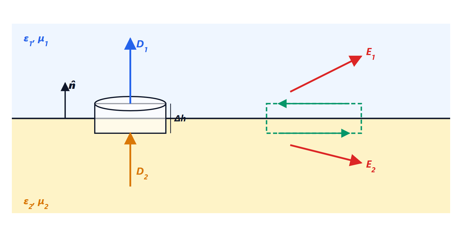
On a small face of area  and normal
 , inside a body, acts a force
 ; the traction vector is
 , measured in pascals (in practice in N/mm² = MPa). It splits into a normal component
 , which pulls or compresses the face, and a shear component
 , which makes it slide.
Cauchy proved that knowing the stresses on three perpendicular faces is enough to obtain them on any face: the nine components form the stress tensor, which is symmetric ( , by rotational equilibrium of an elementary cube), and

Plane stress
In many cases (thin plates, free surfaces, beams) the stresses lie in a plane:  ,
 and
 . On a face whose normal makes angle
 with the
 axis, projecting
 onto the normal and the tangent and using the double-angle formulas:


Mohr’s circle
Theorem. As the orientation varies, the point  describes a circle with centre
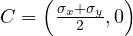 and radius

Proof. Setting  and
 , the previous formulas become
 and
 . Squaring and adding, the cross terms cancel and, since
 , what remains is
 : the equation of a circle. ∎
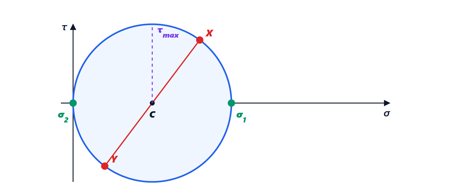
Rotating the face by in the body means rotating by  on the circle. The faces with normals and
 are represented by two diametrically opposite points, X and Y.
Principal stresses
The intersections of the circle with the axis are the principal stresses:
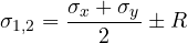
on whose faces the shear stress is zero. The maximum shear stress is the radius  , on faces inclined at 45° to the principal directions.
Example.  MPa,
 MPa,
 MPa. Centre 50, radius
 MPa. Principal stresses
 MPa and
 ; maximum shear 50 MPa. The principal direction is found from
 , i.e.
 and
 .
Principal stresses explain many failures. A twisted piece of chalk breaks along a 45° helix: torsion produces pure shear, corresponding to principal tensile stresses at 45°, and chalk, being brittle, fails in tension. In reinforced concrete shear cracks are inclined for the same reason (Building Techniques lesson on reinforced concrete in shear). Strain-gauge measurements (Electrical Measurements lesson on sensors) are often made with rosettes of three grids at 0°, 45° and 90°, from which the plane state, and hence Mohr’s circle, is reconstructed.