Reinforced concrete: shear and Mörsch's truss
Inclined cracks, the truss model, stirrup resistance proved with an example, compression struts and choice of angle, shift of the moment diagram, detailing rules.
Near the supports reinforced concrete beams crack with cracks inclined at about 45°: shear produces inclined principal tensile stresses (Structural Mechanics lesson on stress), which concrete cannot carry. Without dedicated reinforcement, shear failure is brittle and sudden, and it is one of the most dangerous. In this lesson we look at Mörsch’s truss model, the resistance of stirrups with its proof and an example, the resistance of the compression struts, and detailing rules.
Mörsch’s truss
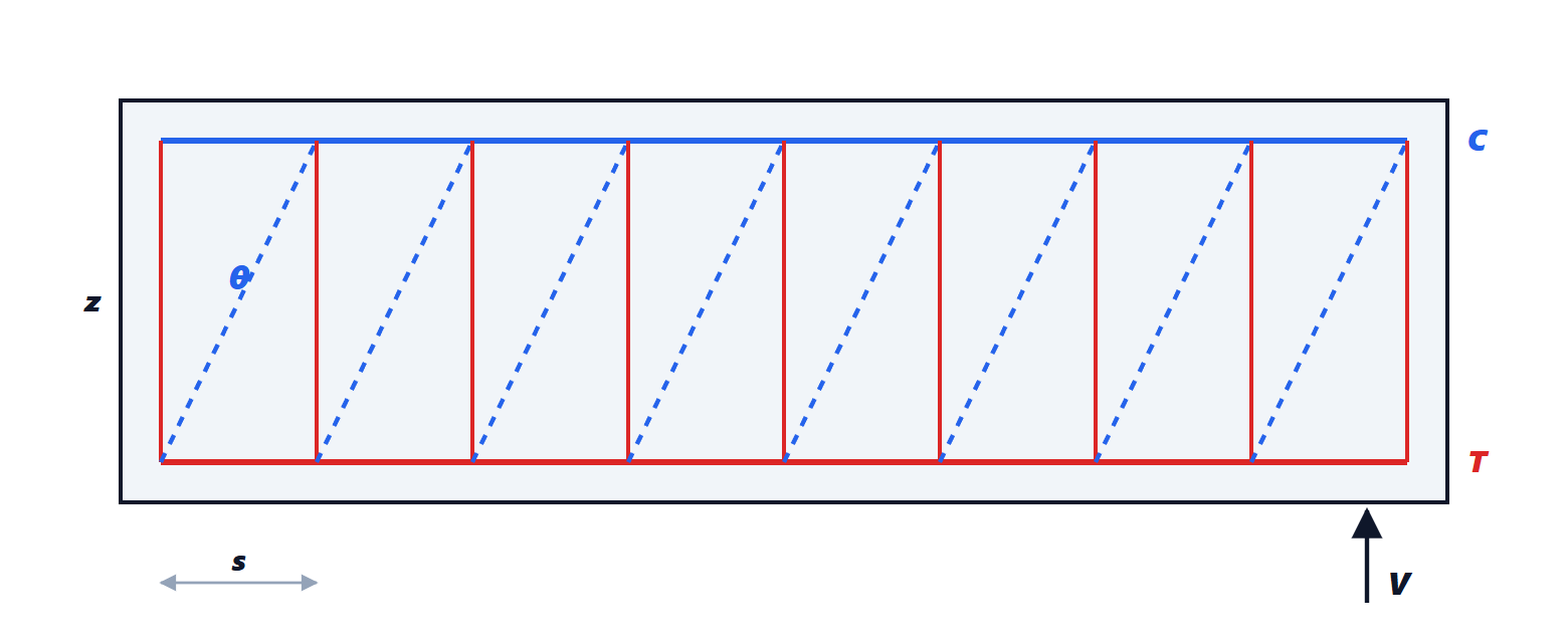
A beam cracked in shear behaves like a truss (Structural Mechanics lesson on statics) hidden inside it:
- the compression chord is the concrete at the top;
- the tension chord is the longitudinal reinforcement at the bottom;
- the struts are the compressed concrete between the cracks, inclined at an angle
 ;
- the ties are the stirrups, the vertical reinforcement “stitching” the cracks.
Stirrup resistance
Theorem. With vertical stirrups of area  (sum of the legs) at spacing
 , the shear resistance due to the reinforcement is

Proof. Cut the beam along a crack inclined at , crossing the depth  between the chords. Its horizontal projection is
 , so the crack crosses
 stirrups. For vertical equilibrium of the part of beam beyond the crack, the shear
 is carried by the cut stirrups (concrete in tension does not work, and the chords are horizontal). If each stirrup has yielded and carries
 , the total force is
 . ∎
Example. The beam of the lesson on bending ( mm) with two-leg 8 mm stirrups (
 mm²) at 200 mm spacing, with
 :
 kN. The design shear at the supports of the 6 m beam with 20 kN/m is 60 kN: verified. Halving the spacing to 100 mm doubles the resistance; this is why stirrups are closer together near the supports, where shear is maximum.
Compression struts
The angle is not fixed: codes allow it to be chosen between about 21.8° and 45° ( ). Flatter struts (larger cotangent) engage more stirrups and increase
 , but compress the concrete more. The strut resistance is

with  the web width and
 a factor accounting for the cracking of the compressed concrete. is chosen so that the two failures, of the stirrups and of the struts, are balanced, or it is checked that the stirrups yield first: stirrup failure is ductile, strut failure brittle. In the example, with
 , rises to about 203 kN and
 kN: the stirrups remain the weak link, as desired.
The same truss explains a less obvious effect: the horizontal component of the struts increases the tension in the bottom chord. The longitudinal reinforcement must therefore be extended beyond the point where the moment alone would require it (shift of the moment diagram) and well anchored at the supports.
Detailing rules
Even when calculation does not require them, codes impose minimum stirrups (for example at least three stirrups per metre and a maximum spacing related to the effective depth), because an element without shear reinforcement fails in a brittle way by diagonal cracking. Stirrups must be closed and anchored with hooks bent inwards; in seismic zones (lesson on seismic design) they must be closer at the ends of beams and columns, where plastic hinges form, because there they confine the concrete, increase its deformation capacity at failure and prevent the compressed bars from buckling.