Steel structures: plastic moment, section classes and buckling
Steels and sections, plastic hinge and the shape factor 1.5 proved, section classes, bending check of an IPE with an example, buckling curves, lateral-torsional buckling, bracing.
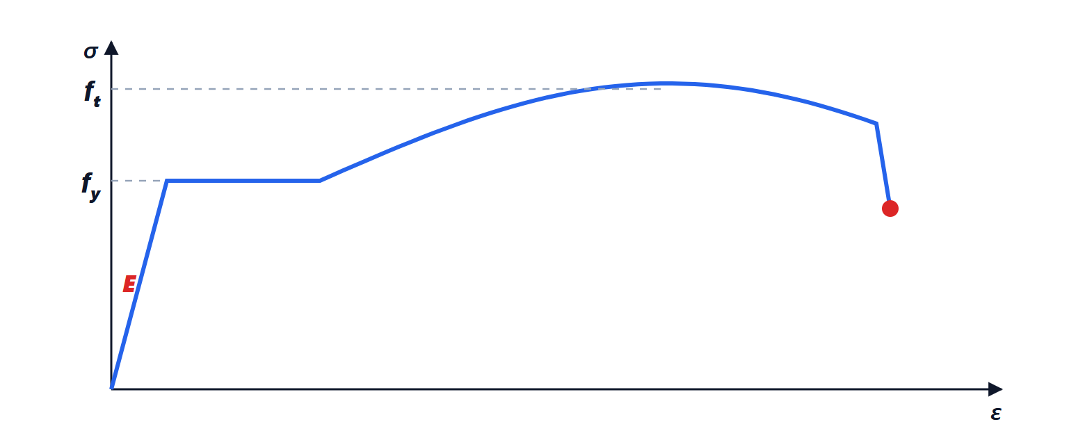
Structural steel allows light structures that are quick to erect and span long distances: industrial sheds, bridges, telecommunication towers, tall buildings. Its ductility (Structural Mechanics lesson on elasticity) allows its strength to be exploited beyond the elastic range. In this lesson we look at steels and sections, the plastic moment with the proof of the shape factor, section classes, the bending check with an example, and member instability.
Steels and sections
The most used structural steels are S235, S275 and S355, where the number is the yield stress in MPa; Young’s modulus is 210 GPa for all. Hot-rolled sections of standard shape are used (I sections: IPE, HEA, HEB; angles, channels, hollow sections) and welded plates for special sections. Their geometric properties (area, moments of inertia, section moduli) are tabulated: for an IPE 300, for example,  cm⁴, elastic modulus
 cm³, plastic modulus
 cm³.
The plastic moment
Increasing the moment beyond the elastic limit, the outermost fibres yield and keep deforming at constant stress  , while yielding spreads inwards. In the limit the whole section has yielded: half at
 , half at
 . The corresponding moment is the plastic moment
 , and the section rotates without any further increase in moment: a plastic hinge has formed.
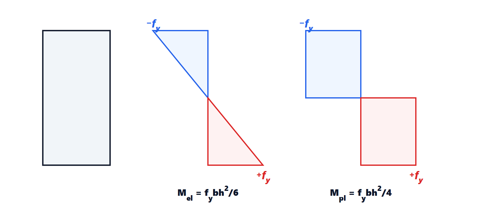
Theorem. For a rectangular section  the ratio between the plastic moment and the moment at first yield, the shape factor, is 1.5.
Proof. At first yield the distribution is linear with at the edges, and  (Structural Mechanics lesson on bending). In the plastic distribution, the compressed half carries the force
 applied at
 from the neutral axis, and the tensile half an equal and opposite force at on the other side: the lever arm of the couple is
 , and
 . The ratio is
 . ∎
For an I section, with the material already concentrated in the flanges, the shape factor is lower, about 1.13-1.15 (for IPE 300,  ): the section is already efficient in the elastic range.
Section classes
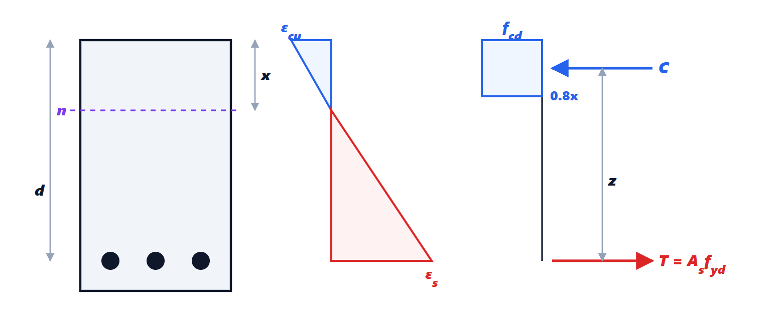
A section can reach the plastic moment only if its thin compressed parts do not buckle locally first (Structural Mechanics lesson on instability). Codes classify sections according to the width-to-thickness ratios of the compressed parts:
- class 1: reach the plastic moment and have rotation capacity, suitable for plastic analysis;
- class 2: reach the plastic moment, with limited rotation capacity;
- class 3: reach only yielding of the extreme fibres (
 is used);
- class 4: buckle locally before yielding (a reduced effective section is used).
Common hot-rolled sections in bending are almost all class 1.
The bending check

Example. An IPE 300 beam in S275 over a 6 m span, with a design load of 30 kN/m:  kNm.
 kNm: verified, with a utilisation ratio of 82 %. Then shear, carried by the web, deflection at the serviceability limit state (Structural Mechanics lesson on the elastic line), and instability are checked.
Member instability
Steel structures are slender, and instability often governs their design.
- Compression members are checked with
 , where the factor
 depends on the non-dimensional slenderness and on the buckling curve of the section type and axis, which accounts for geometric imperfections and residual rolling stresses.
- Beams in bending with the compression flange not restrained laterally can undergo lateral-torsional buckling: the compressed part moves sideways and the section twists. It is checked in a similar way, with a factor
 ; the remedy is to restrain the compression flange with the floor, with bracing or with cross beams.
- Members in combined compression and bending (frame columns) require interaction formulas combining the two effects.
Overall stability of the building is ensured by bracing (diagonals, walls, cores) carrying horizontal wind and seismic actions to the foundations, or by moment-resisting frames.