ACC 1: function, ISO requirements, state machine and AUTOSAR architecture
What an ACC with stop & go does, the limits of ISO 15622 and ISO 22179, the four time gaps, the complete state machine, AUTOSAR components, ECUs, E2E protection and the timing budget.
https://www.electronics-engineering.com/en/acc-adaptive-cruise-control-requirements-state-machine-autosar/
ACC (Adaptive Cruise Control) keeps the speed chosen by the driver and, when a slower vehicle is ahead, follows it at a distance proportional to speed. It sounds simple, but behind it there is a complete chain: sensors, data fusion, choice of the target, planning of the manoeuvre and control of the torque at the wheels. This is the first of seven lessons that build a real ACC, from the radar to the brakes, with Python and C code that works and has been tested on test scenarios. Here we look at what the function must do, the requirements of the standards, the state machine and how the software is organised in AUTOSAR.
What an ACC does
The driver sets a speed  and a time gap
 . The system works in two ways:
- speed control: free road, the car holds like an ordinary cruise control;
- following: a slower vehicle is ahead, the car follows it at the distance
 , where
 is the distance at standstill (about 4 m) and
 our speed.
The time gap is the time we would need to reach the point where the vehicle ahead is now: with  s at 100 km/h (27.8 m/s) the desired distance is
 m. The driver picks it with a button among four values: short 1.0 s, middle 1.4 s, long 1.8 s, extra long 2.2 s. Every start begins at “long”.
With stop & go (Full Speed Range ACC) the function works down to standstill: it stops behind the vehicle ahead, holds the car with the brakes, drives off by itself after a short stop and asks the driver to confirm after a long one.
ACC is an assistance system, not emergency braking: it decelerates by a few m/s² at most and the driver remains responsible. Sudden obstacles are the job of another function, AEB (automatic emergency braking), which shares requirements and sensors.
The requirements of the standards
The reference standards are ISO 15622 (ACC) and ISO 22179 (full speed range ACC, with stop & go). They set comfort and safety limits that the software must respect in every case:
| Quantity | at 20 m/s and above | at 5 m/s and below |
|---|---|---|
| maximum acceleration | 2.0 m/s² | 4.0 m/s² |
| maximum deceleration (average over 2 s) | 3.5 m/s² | 5.0 m/s² |
| maximum jerk when braking | 2.5 m/s³ | 5.0 m/s³ |
| minimum steady-state time gap | 0.8 s | 0.8 s |
Between 5 and 20 m/s the limits are interpolated linearly. The standard also requires at least one time gap setting between 1.5 and 2.2 s (our “long” and “extra long”), that the driver can always override (accelerator and brake pedal) and that the function signals when it cannot handle a situation.
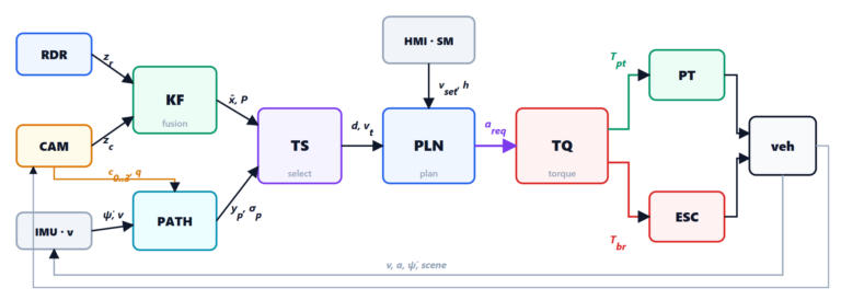
The functional chain
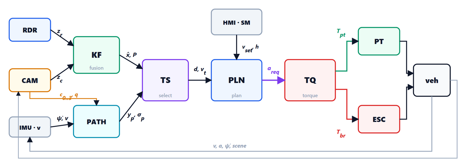
 ,
 ; the Kalman filter (KF) fuses them into objects with state
 and covariance
 ; the predicted path (PATH) comes from yaw rate
 , speed and lane lines; target selection (TS) chooses the vehicle to follow; the planner (PLN) computes the acceleration request
 ; the torque controller (TQ) splits it between powertrain (PT) and brakes (ESC). The vehicle closes the loop back to the sensors.
Each block has a lesson:
- this one: requirements, state machine, architecture;
- sensors and configurations (camera only, camera and radar, several cameras and several radars);
- fusion: tracking with the Kalman filter, association, track management;
- target selection: predicted path, probability of being in the lane, cut-ins and false positives;
- planning and longitudinal control: following, string stability, elastic approach, overtaking preboost, stop & go;
- from the acceleration request to the wheel torque: vehicle physics, three powertrain/brake zones, grade and mass estimation;
- integration: the complete system tested on scenarios with measurable criteria.
The function state machine
The state machine decides when ACC actually controls the vehicle. It is the most safety-related part: a mistake here means a car that brakes or accelerates when the driver does not expect it.
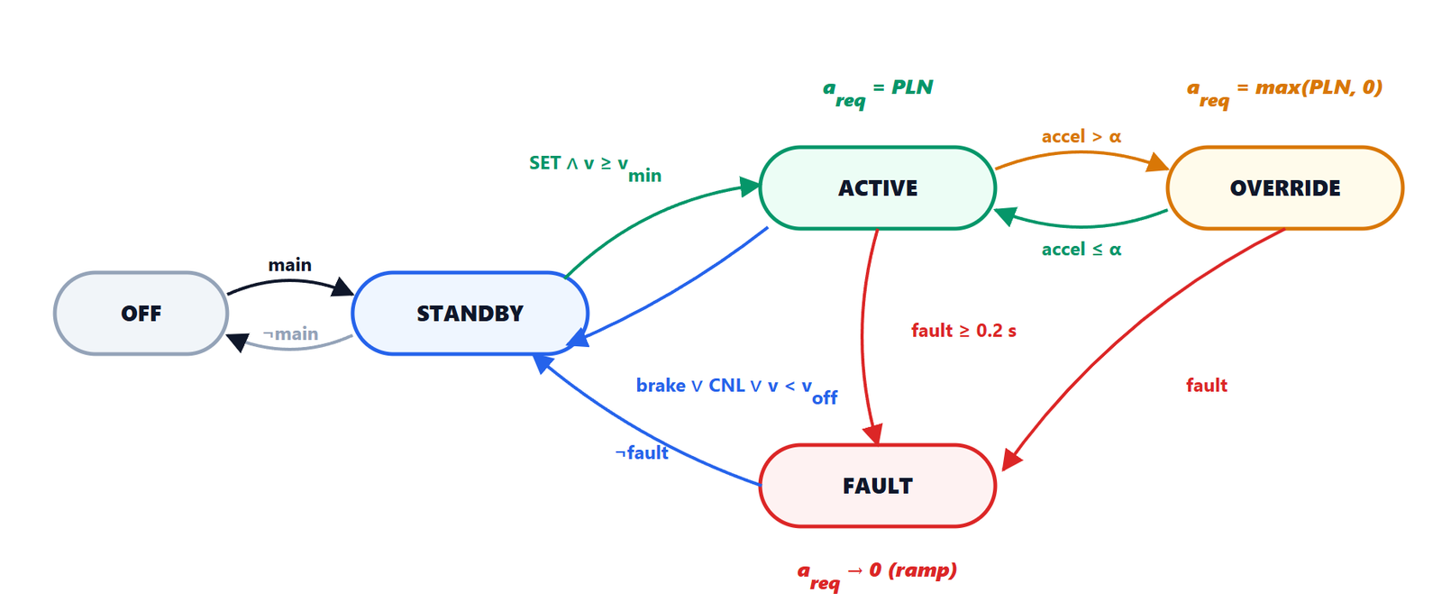 ) or RES; OVERRIDE when the driver presses the accelerator beyond the threshold α; back to STANDBY with the brake, CANCEL or (without stop & go) below
 ; FAULT if a sensor or the ESC is no longer available for at least 0.2 s. In FAULT and on exit the request goes back to zero with a ramp, never with a step.
| State | What happens | Output to the controller |
|---|---|---|
| OFF | function off | none |
| STANDBY | ready, not in control | ramp to 0 |
| ACTIVE | holds or follows the vehicle ahead | planner |
| OVERRIDE | the driver accelerates | positive values only: ACC does not brake |
| STANDSTILL | stopped behind a vehicle (stop & go) | held by the brakes; automatic drive-off within 3 s |
| WAIT | stopped for more than 3 s | held; drives off with RES or a touch of the accelerator |
| FAULT | a needed condition is lost | ramp to 0 with jerk ≤ 2 m/s³, driver warning |
A few details make the difference between an exercise and a real function:
- set speed: SET takes the current speed rounded to the km/h (never below 30 km/h); in ACTIVE, SET and RES lower or raise it by 1 km/h;
- fault debounce: a sensor blind for a single cycle does not switch the function off, one blind for 0.2 s does;
- no steps on exit: when the function is disengaged while braking, the request goes back to zero with limited jerk, so that the driver has time to take over;
- long stop: after 180 s in WAIT the electric parking brake (EPB) replaces the service brakes and the function goes to STANDBY.
The Python code of the state machine is in acc_sim.py (class AccStateMachine), the C code in acc.c (function AccSm_Run); lesson 7 tests them one by one.
The AUTOSAR architecture
In cars the ECU software follows the AUTOSAR standard. In the Classic platform, used on microcontrollers with a real-time operating system, the application software is divided into software components (SWC) that communicate only through ports; the RTE (Run-Time Environment) connects the ports and triggers the functions of the components, called runnables, at fixed intervals or when data arrive. Below are the basic software modules (BSW) for bus communication, operating system, diagnostics and memory.
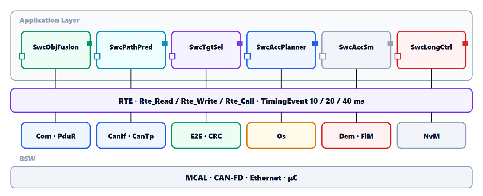
A runnable never calls another component directly: it reads and writes through the RTE. This is how the longitudinal control runnable (executed every 20 ms) looks in our C code:
/* SwcLongCtrl, runnable at 20 ms (TimingEvent) */
void SwcLongCtrl_Run20ms(void)
{
    float a_req, v, a_imu, t_pt, t_br;
    boolean hold;
    Rte_Read_AccelRequest_Value(&a_req);       /* from component SwcAccSm */
    Rte_Read_StandstillHold_Value(&hold);
    Rte_Read_VehicleSpeed_Value(&v);           /* from the ESC, on CAN */
    Rte_Read_LongAccelImu_Value(&a_imu);
    LongCtrl_Run(&ctrl, a_req, v, a_imu, hold, &t_pt, &t_br);
    Rte_Write_PowertrainTorqueReq_Value(t_pt); /* to the engine ECU */
    Rte_Write_BrakeTorqueReq_Value(t_br);      /* to the ESC */
}
All the logic is in LongCtrl_Run, which knows nothing about buses or operating systems: it is tested on a PC exactly as it runs in the ECU. The same principle applies to all the code of these lessons.
On which ECUs
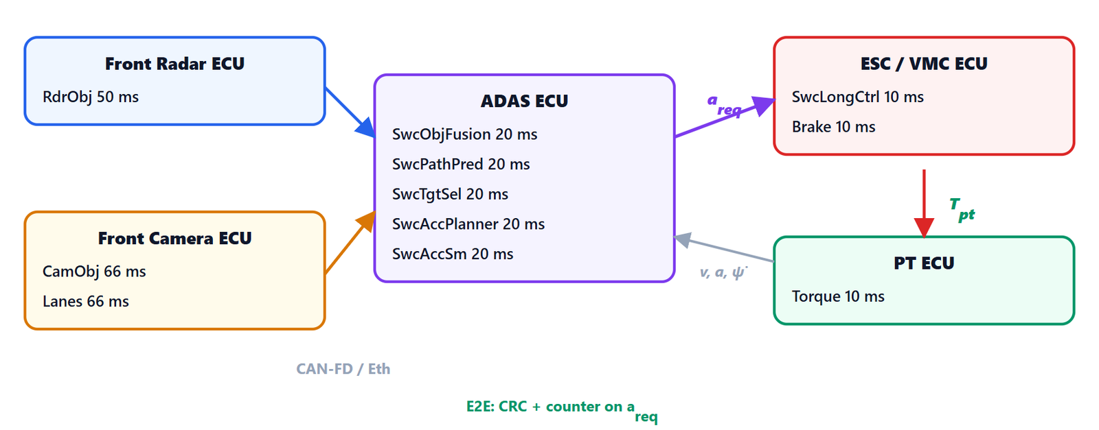
There is a reason for this split: torque control sits close to the actuators (ESC), where the fast wheel signals are and where ABS and ESP already run; the ACC function sits where the sensor data arrive. In vehicles with a powerful central computer (zonal architecture) fusion and planning often run on AUTOSAR Adaptive, on Linux or a similar system, and talk to the rest through services (ara::com); torque control stays on a microcontroller in Classic.
Signal protection and functional safety
A wrong acceleration request can make the car brake or accelerate for no reason: it is a hazard that ISO 26262 classifies, depending on the manufacturer’s analysis, typically up to ASIL B. Therefore:
- the request travels with E2E protection (CRC over the content, a counter that changes with every message): the receiver detects corrupted, repeated or lost messages;
- the receiver has a timeout: if the request does not arrive for more than a few cycles, the function goes to FAULT and the request returns to zero with a ramp;
- the ESC limits the request to the values of the standard anyway (deceleration and jerk), whatever arrives;
- errors go to the diagnostic event manager (Dem) and the function inhibition manager (FiM) disables ACC when a needed sensor is degraded (blinded camera, dirty radar).
The timing budget
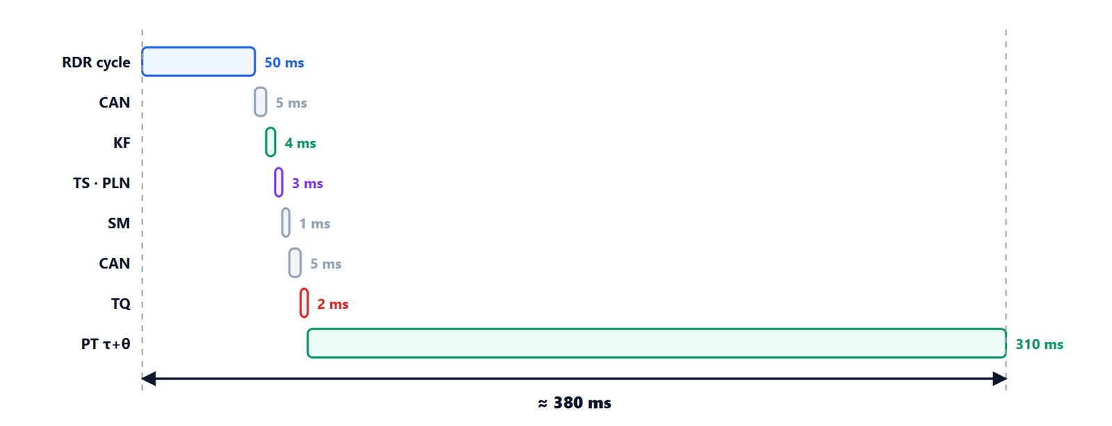
The dominant delay is not the software but the actuator: the engine responds with a time constant of about 0.25 s plus a dead time, the brakes faster (about 0.12 s), but only after the pads have reached the disc. Every delay in the loop takes away phase margin (we saw it in the lesson on implementing digital controllers) and in lesson 5 we will see that it worsens the string stability of a line of vehicles: it is one of the reasons why the minimum time gap is 0.8 s and not less.
The code that comes with the lessons
All the lessons use the same code, which really works:
acc_sim.py: the whole chain in Python (numpy only): vehicle model with engine, brakes, wind, grade and payload; radar and camera; Kalman tracker; path prediction; target selection with state machine; planner; torque control; function state machine. Each block is a class with astep()method, like a runnable;make_plots.py: all the charts of these lessons, computed with the simulation;test_scenarios.py: 14 test scenarios with measurable criteria (lesson 7), all passed;acc.h,acc.c,test_acc.c: the same chain in C99 as AUTOSAR components, compiled without warnings and tested on 13 scenarios with the same results as the Python version.
Download the complete code (zip, 42 kB), with instructions to run it.
In the next lesson we start from the first block: what a camera and a radar see, how precisely, and why configurations with several sensors are not only about seeing further.