Diode circuits: rectifiers, Zener, protection, LEDs and solar cells
Half-wave and bridge rectifiers, ripple with an example, the Zener regulator, clippers and protection, LEDs with a series resistor, photodiodes and solar cells.
The one-way behaviour of the diode underlies circuits found everywhere: power supplies that turn the AC mains voltage into DC, voltage regulators, input protection, and then diodes that emit and absorb light. In this lesson we analyse them with the simple models from the previous lesson.
The half-wave rectifier
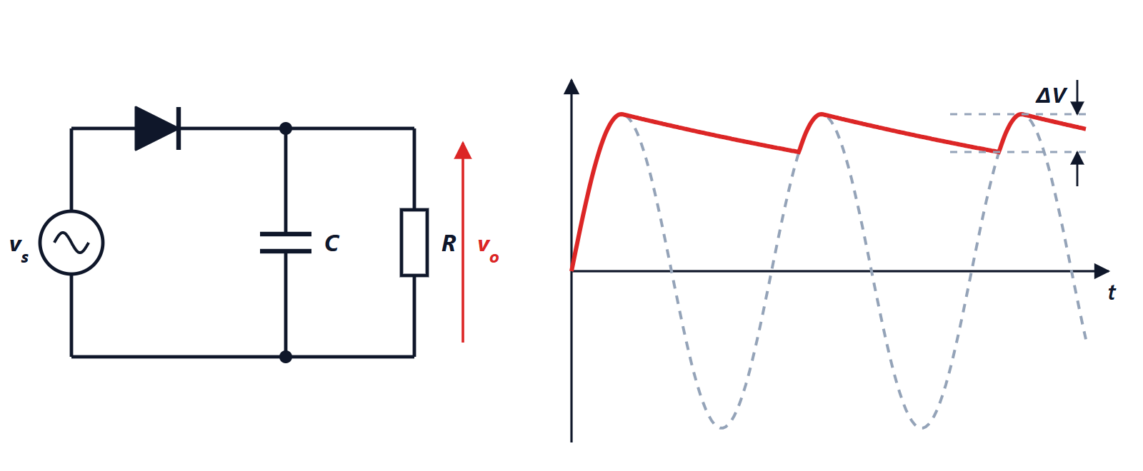
A sinusoidal source, a diode and a load in series: when the voltage is positive the diode conducts and the load sees the positive half-wave (minus about 0.7 V); when it is negative the diode is off and there is no voltage across the load. The output has a non-zero average, but it pulses.
To make it almost constant, a capacitor is added in parallel with the load. During the peak the diode conducts and charges the capacitor to the peak voltage; then the sinusoid falls, the diode turns off and the capacitor supplies the load, slowly discharging, until the next peak recharges it.
Ripple
Calculation. If the ripple  is small, the capacitor supplies an almost constant current
 to the load for nearly the whole period
 between two recharges. The charge lost is
 , and from
 :

where  is the recharge frequency: 50 Hz for the half-wave rectifier, 100 Hz for the full-wave one.
The bridge rectifier. Four diodes in a bridge pass both half-waves through the load, always in the same direction. The recharge frequency doubles and the ripple halves, but the current goes through two diodes in series and the drop becomes about 1.4 V.
Example. A 12 V RMS transformer, a bridge, a 0.5 A load, a 4700 µF capacitor. Peak:  V. Ripple:
 V. The output swings between about 14.5 and 15.6 V; a regulator downstream then brings it to a stable value, for example 12 V.
An important detail: the diode conducts only for a small fraction of the period, near the peak, with current pulses much higher than the average current. This is the cause of the low power factor of power supplies, discussed in the Electrical Engineering lesson on power.
The Zener regulator
A series resistor  and a Zener diode in parallel with the load: the Zener in breakdown holds an almost constant voltage
 across it, and absorbs the excess current.
Example. 12 V input, 5.1 V Zener,  Ω. The current in is
 mA. With a load drawing 20 mA, 11.4 mA flows in the Zener. If the load asks for more than 31.4 mA, regulation is lost; if the load is disconnected, the Zener must dissipate
 W.
It is simple but inefficient; today it is used mainly as a voltage reference, while power is handled by integrated linear regulators or switching converters.
Clippers and protection
- Clipper: two antiparallel diodes to ground clip a signal at about ±0.7 V. They protect sensitive inputs.
- Electrostatic discharge protection: every pin of an integrated circuit has two diodes, to the supply and to ground, that divert overvoltages.
- Flyback diode: in parallel with the coil of a relay or a motor, it gives the inductor current a path when the driving transistor turns off, avoiding the overvoltage seen in the lesson on transients.
- Reverse polarity protection: a diode in series with the supply blocks the current if the battery is fitted the wrong way round.
Diodes and light
LED. In a direct-gap semiconductor recombination emits light with energy close to the gap: red with a threshold of about 1.8 to 2 V, blue and white with about 3 V. An LED is driven with current: given the exponential characteristic, a small voltage change would change the current a lot. The simplest way is a series resistor: with a 5 V supply, a 2 V red LED and 10 mA wanted,  Ω.
Photodiode. Reverse biased, its current is proportional to the light received: barcode readers, remote controls, optical fibres, light sensors.
Solar cell. The same junction with no supply. Light generates a current  that flows opposite to the diode’s forward current:

With an open circuit ( ) the voltage is
 : with
 mA and
 A,
 V. That is why panels put dozens of cells in series. Maximum power is obtained at a voltage a little below
 , and the inverter’s job is to keep searching for that point (MPPT, maximum power point tracking).