Frequency modulation, PLLs and synthesisers
The FM spectrum and Bessel functions, FM's noise advantage, pre-emphasis, the phase-locked loop and its uses, integer and fractional-N frequency synthesisers.
Frequency modulation trades bandwidth for quality, and modern receivers need precise, electronically tunable oscillators. Both topics lead to the same circuit, the phase-locked loop (PLL), found in every radio, phone, computer and network card. In this lesson we cover the FM spectrum, FM’s advantage in noise, how the PLL works and the frequency synthesiser.
The FM spectrum
With a sinusoidal message of frequency  and deviation
 , the FM signal is

where  is the modulation index. Expanding in a Fourier series, the spectrum contains the carrier and infinitely many side lines at
 , with amplitudes given by the Bessel functions
 . In practice the significant lines are about
 on each side, hence Carson’s rule
 seen in Signal Theory. Unlike AM, FM is not linear: its bandwidth depends on the message amplitude, not just on its bandwidth.
A curious fact: for certain values of (the first is about 2.405)  and the carrier vanishes from the spectrum. This is used to calibrate transmitter deviation.
The noise advantage
The FM receiver ignores amplitude (with a limiter) and measures the instantaneous frequency. Noise shifts the signal phase by an amount inversely proportional to the carrier amplitude, and frequency is the derivative of phase: the output noise grows with frequency (“triangular” in amplitude, parabolic in power). The result, above a threshold of about 10 dB of input SNR, is a signal-to-noise improvement proportional to  compared with AM for the same power: with
 , as in broadcast radio, more than 25 dB. It is the bandwidth-quality trade that Shannon’s formula formalises. To exploit it better, high frequencies are boosted in transmission and attenuated in reception (pre-emphasis and de-emphasis), reducing noise where it is strongest.
The phase-locked loop
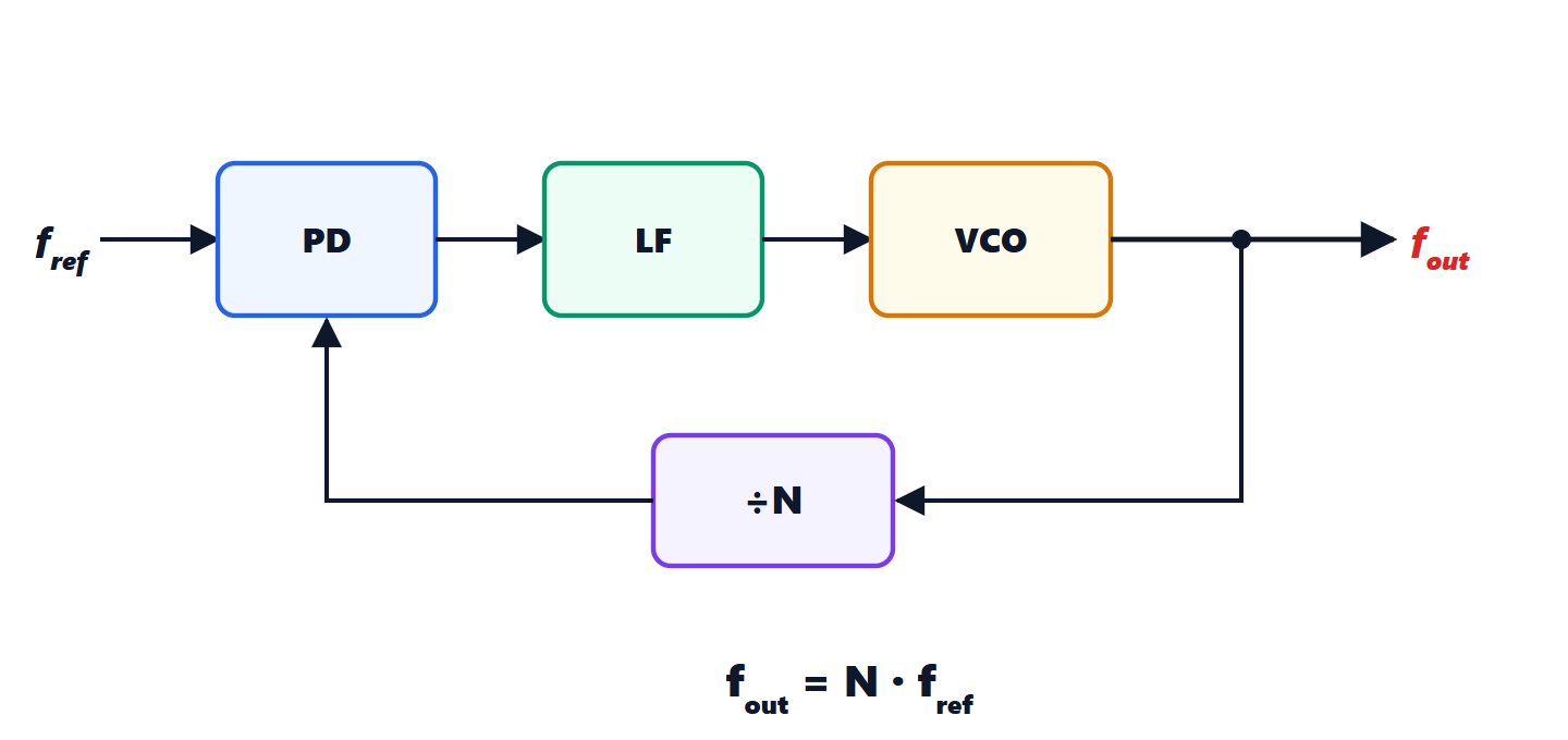
A PLL is a control system (Automatic Control lessons) in which the controlled quantity is the phase of an oscillator:
- the phase detector (PD) produces a voltage proportional to the phase difference between the reference and the fed-back signal;
- the loop filter (LF) filters it and sets the loop dynamics;
- the voltage-controlled oscillator (VCO) changes frequency in proportion to the control voltage.
Since phase is the integral of frequency, the VCO contains an integrator: if the loop is stable, in steady state the phase error is constant and the frequencies are exactly equal. The oscillator “tracks” the reference: the loop is said to be locked.
Uses of the PLL.
- FM demodulator: locked to the received signal, the VCO control voltage follows the instantaneous frequency, that is it is the demodulated message.
- Carrier and clock recovery: it regenerates the carrier for coherent demodulation, or the symbol timing from the received data (every USB, SATA, Ethernet port has one).
- Jitter cleaning: with a narrow loop filter, the output follows slow reference variations and ignores fast ones.
The frequency synthesiser
Inserting a divide-by-N in the feedback path, the loop locks when  :

With a 100 kHz crystal and  one gets exactly 2.4 GHz, with the crystal’s stability; changing
 by 1 moves to the next channel 100 kHz away. Fractional-N synthesisers switch between two integers following a sequence that on average gives a non-integer value, achieving very fine steps without lowering the reference frequency. Every phone has several, for the various bands; the same principle generates the gigahertz clocks of processors from a crystal of a few tens of megahertz.