Phased arrays: array factor, grating lobes, PIN-diode phase shifters, monopulse and active arrays
Electronic steering explained simply, the array factor proved, beamwidth and its broadening with steering, the condition against grating lobes proved, PIN-diode digital phase shifters and quantisation error, monopulse, PESA, AESA and digital arrays.
A radar with a rotating parabolic antenna looks in one direction at a time and takes seconds for a full turn. A phased array radar is made of hundreds or thousands of small antennas side by side; by changing electronically the phase with which each one transmits and receives, the beam moves in microseconds, with no moving parts. A single radar can thus track tens of targets, search for new ones and guide missiles almost simultaneously. This lesson derives the array factor, the steering law and the beamwidth, proves the condition against grating lobes, explains the diode phase shifters that implement the phase delays and their quantisation, and introduces monopulse angle measurement and active and digital arrays.
The idea in simple words
Picture a row of people on a beach throwing stones into the water at the same instant: the waves of all the stones add up, and a straight, strong wave leaves in front of the row. If instead each person throws a moment after the one on their left, the resulting wave leaves at a slant, towards the right: without anyone turning, the direction of the wave has changed. A phased array does exactly this with radio waves: each small antenna transmits with a small delay (a phase shift) relative to its neighbour, and the beam points in the desired direction. Changing the phase shifts takes microseconds, so the beam jumps from one direction to another almost instantly.
In reception the same holds in reverse: an echo arriving at a slant reaches one end of the row first and then the other; by suitably delaying the signals of the antennas before adding them, the array “listens” only to the desired direction. The antennas must however be close enough (about half a wavelength), otherwise the array also listens to other, ghost directions: these are the grating lobes.
The steering geometry
Consider  antennas in a line a distance
 apart, receiving a plane wave from direction
 (measured from the normal to the array). The wavefront reaches element
 after travelling a path longer by
 than element 0: each element receives the signal with a phase delayed by
 , with
 . If a phase shift
 is added to each element and the outputs are summed, for
 all contributions arrive in phase and add up to the maximum: the beam “points” towards
 .
The array factor
Theorem. The normalised response of the array steered towards is

Proof. The sum of the contributions is  , a geometric series:
 (factoring
 out of the numerator and
 out of the denominator, as for the Dirichlet kernel of the DFT). The magnitude, divided by its maximum , is the formula. ∎
The consequences for design:
- beamwidth at −3 dB about
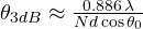 : for 32 elements at half a wavelength, 3.17° at broadside, 3.66° steering to 30°, 6.4° at 60°. The beam widens as it tilts, because the array seen obliquely looks shorter (factor
 ): this is why flat arrays cover about ±60° in practice and naval radars use four of them on different faces;
- sidelobes at −13.2 dB, as for the sinc: they are lowered by weighting the amplitudes (Taylor or Chebyshev windows), widening the beam slightly;
- phase shift between elements
 : for
 and 30°, 90° from one element to the next.
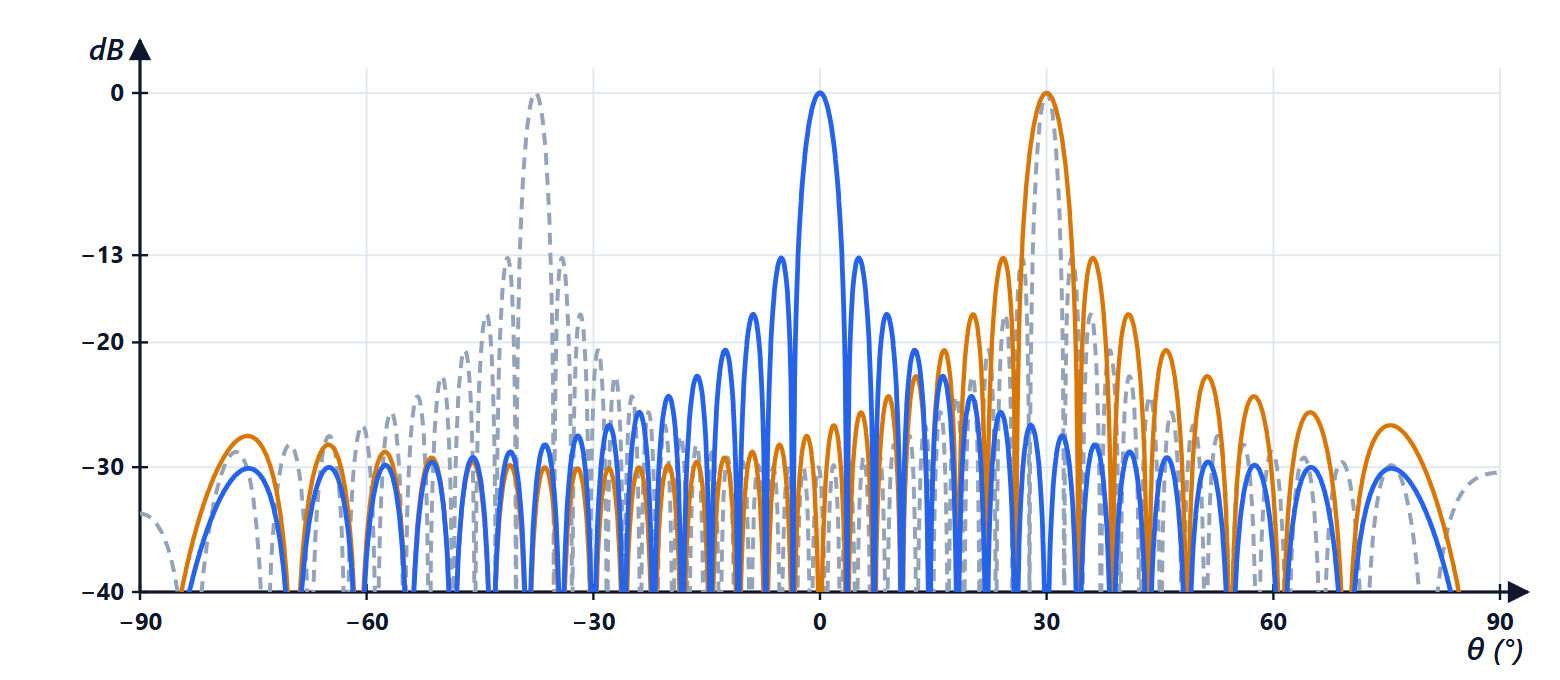
Grating lobes
 is periodic in
 with period
 : besides the main beam (
 ) there are equal maxima where
 . These are the grating lobes: copies of the beam in other directions, which would see ghost targets.
Theorem. An array steered up to  has no grating lobes in visible space if
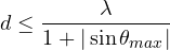 .
Proof. The first grating lobe is at  , that is
 . It exists in visible space if
 . The worst case is with the beam tilted by and the lobe on the other side:
 brings it inside; the condition to keep it out is
 . ∎
With there are no grating lobes for any steering angle; with  only up to 25.4°; with
 not even at broadside (the lobe is at 90°). Half a wavelength is therefore the standard spacing: in X band, 1.5 cm between elements.
Diode phase shifters
The phase shift of each element is produced by a phase shifter. The most common use PIN diodes, which at microwave frequencies behave as switches: forward biased they have a resistance of a few ohms, reverse biased a small capacitance. Digital phase shifters are built in bits:
- switched line: two diodes select between two line sections of different length; the length difference
 gives a phase shift
 ;
- loaded line: the diodes insert small reactances along the line, suited to small bits (22.5°, 45°);
- reflection type, with a hybrid coupler and two identical diodes.
Cascading bits of 180°, 90°, 45° and 22.5° gives a 4-bit phase shifter with 16 values. The desired phase must be rounded to the nearest value: with step  ° the error is uniform between
 , with rms value
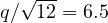 °. Quantisation errors raise the sidelobes and, if they repeat periodically along the array, create quantisation lobes; they are attenuated by adding a known random phase to each element. In recent radars the phase is set in the integrated circuits of the modules and, in digital arrays, directly in numerical form.
A fundamental limit of phase: the right phase shift depends on frequency. With wideband signals the beam “points” in slightly different directions at the various frequencies (beam squint). Wideband radars use true time delay lines, which delay the signal by a time and not by a phase.
Monopulse angle measurement
To track a target it is not enough to know that it is in the beam: the precise angle is needed. Monopulse splits the antenna into two halves and forms, with a single pulse, two beams: the sum  of the two halves and the difference
 . With the two halves a distance
 apart and a target at a small angle from the axis, the two halves receive with a phase difference
 , and

(with the same factoring of  as for the MTI canceller). The ratio is proportional to the angle error, and its sign (given by the relative phase of with respect to ) tells which side. With
 m in X band, for 0.5° the ratio is 0.49 (linear 0.46): the relation is linear for errors small compared with the beamwidth. Monopulse measures the angle with an accuracy of a fraction of the beamwidth, is insensitive to amplitude fluctuations of the echo (because it is a ratio) and is done in two planes (azimuth and elevation) with four quadrants.
Active and digital arrays
- PESA (passive array): a single transmitter, whose power is divided among the elements, each with its phase shifter.
- AESA (active array): each element has a T/R module (transmit/receive) with power amplifier, low-noise amplifier, phase shifter and attenuator. More reliable (a failed module reduces performance only slightly), more efficient, able to form several beams at once. With gallium nitride (GaN) transistors it is today the standard of military radars and of many civil ones.
- Digital array: the signal of each element (or subarray) is converted to digital, and the beams are formed in the computer by products with complex weights. Many receive beams can be formed simultaneously, a jammer can be cancelled by steering a null towards it (adaptive beamforming), and the array can be combined with MIMO processing (lessons on FMCW radars and on digital radar).
Summary
- Phasing the elements by from one to the next steers the beam towards without moving the antenna.
- The array factor is a Dirichlet kernel: beamwidth about
 , sidelobes at −13.2 dB without weighting.
- The beam widens when steered away from broadside: a flat face covers about ±60°.
- To avoid grating lobes
 is required: half a wavelength works for every steering angle.
- PIN-diode digital phase shifters have a quantisation error (6.5° rms with 4 bits); wide bandwidths need true time delays.
- Monopulse measures the angle with a single pulse from the difference-to-sum ratio.
- Active arrays (AESA) have one T/R module per element; digital ones form the beams in the computer.
The code
import numpy as np

c = 299792458.0
lam = c / 10e9                                       # X band
N, d = 32, lam / 2
theta = np.radians(np.linspace(-90, 90, 36001))

def array_factor(steer, d=d):
    psi = 2 * np.pi * d / lam * (np.sin(theta) - np.sin(np.radians(steer)))
    with np.errstate(invalid="ignore", divide="ignore"):
        a = np.abs(np.sin(N * psi / 2) / (N * np.sin(psi / 2)))
    return np.where(np.isnan(a), 1.0, a)             # in the limit psi -> 0 it equals 1

for steer in (0, 30, 60):
    deg = np.degrees(theta[array_factor(steer) >= 1 / np.sqrt(2)])
    main = deg[np.abs(deg - steer) < 10]             # main beam only
    print(f"steering {steer:2d} degrees: width {main.max() - main.min():.2f} degrees, "
          f"formula {np.degrees(0.886 * lam / (N * d * np.cos(np.radians(steer)))):.2f}")
a = array_factor(0)
print(f"first sidelobe: {20 * np.log10(a[np.abs(np.degrees(theta)) > 4].max()):.1f} dB")
print(f"phase shift between elements for 30 degrees: {360 * d / lam * np.sin(np.radians(30)):.0f} degrees")
for dd in (0.7, 0.9):
    print(f"d = {dd} lambda: no grating lobes up to {np.degrees(np.arcsin(1 / dd - 1)):.1f} degrees")
print(f"4-bit phase shifter: 22.5 degree step, rms error {22.5 / np.sqrt(12):.2f} degrees")

D = 0.5                                              # monopulse: two halves 0.5 m apart
for err in (0.25, 0.5, 1.0):
    phi = 2 * np.pi * D / lam * np.sin(np.radians(err))
    print(f"error {err} degrees: Delta/Sigma = {np.tan(phi / 2):.3f}, linear {np.pi * D * np.radians(err) / lam:.3f}")
Running it prints the widths 3.17, 3.66 and 6.38° (formula 3.17, 3.66 and 6.35), the sidelobe at −13.2 dB, 90°, 25.4° and 6.4° for spacings 0.7λ and 0.9λ, 6.50° of rms error, and for monopulse 0.23, 0.49 and 1.30 against 0.23, 0.46 and 0.91 of the linear approximation.





