Two-terminal elements and conventions: resistor, sources, capacitor and inductor
Voltage, current and two-terminal elements, passive and active sign conventions, power, Ohm's law, ideal sources, capacitor and inductor, real components.
Circuit theory studies circuits as networks of ideal components, described only by the relation between voltage and current at their terminals. It is a powerful abstraction: it does not matter how a resistor or a battery is built inside, only how it behaves seen from outside. In this lesson we introduce the quantities, the sign conventions (a source of many mistakes), the basic ideal two-terminal elements and power.
Voltage, current and two-terminal elements
A two-terminal element (or one-port) is a component with two terminals. Its state is described by two quantities:
- the current
 through it (in amperes), with a chosen direction shown by an arrow;
- the voltage
 across its terminals (in volts), with one terminal marked + as reference.
The directions are reference directions: they are chosen at the start, and if a quantity turns out negative it only means the actual direction is opposite to the chosen one. What matters is to choose them first and stick to them to the end.
Sign conventions and power
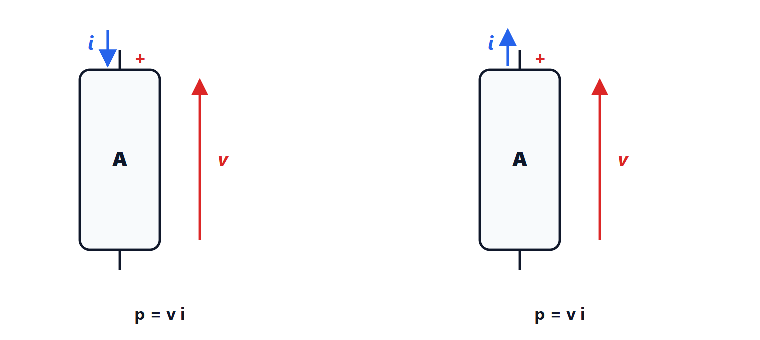
- Passive sign convention: current enters the + terminal. The product
 is the power absorbed by the element.
- Active sign convention: current leaves the + terminal. The product is the power delivered.
With the passive convention, a negative power means the element is actually delivering energy: a battery feeding a circuit absorbs a negative power. In an isolated circuit the sum of the powers absorbed by all elements is zero (Tellegen’s theorem): the energy delivered by the sources equals that absorbed by the other components.
The resistor
With the passive convention the ideal resistor follows Ohm’s law:

 is the resistance in ohms,
 the conductance in siemens. The absorbed power is
 , always positive: a resistor always dissipates energy, as heat. The limiting cases are the short circuit (
 , zero voltage for any current) and the open circuit (
 , zero current for any voltage).
With real resistors the power rating matters too: a 1/4 W resistor of 100 Ω with 10 V across it would dissipate 1 W and burn out.
Ideal sources
- Ideal voltage source: keeps the voltage
 across it whatever current flows through it. It cannot be short-circuited (the current would be infinite).
- Ideal current source: drives the current
 whatever voltage appears across it. It cannot be left open-circuited (the voltage would be infinite).
A real voltage source is modelled as an ideal source in series with an internal resistance  : at the terminals you measure
 . The voltage drops as the current rises: the “sag” you notice starting a car with an old battery. The same source can be seen as a current source
 in parallel with : the two models are equivalent, a preview of the Thevenin and Norton theorems.
Elements with memory: capacitor and inductor
The ideal capacitor and inductor link voltage and current through a derivative (Physics 2):
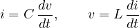
They do not dissipate energy but store it:  in the electric field,
 in the magnetic field. Two practical consequences:
- the voltage on a capacitor cannot change abruptly (it would need an infinite current): it is continuous in time;
- the current in an inductor cannot change abruptly: it is continuous too.
In DC, at steady state, nothing changes: the capacitor behaves as an open circuit, the inductor as a short circuit. These are the rules we will use for transients.
Real components
Every real component departs a little from the ideal one: a resistor has a small inductance, a capacitor a series resistance (ESR), an inductor the resistance of its wire. At low frequency ideal models are enough; at high frequency the “parasitic” elements matter, and a 100 nF capacitor, above a few tens of megahertz, already behaves like an inductor. Component values are read from the codes printed on the body, like the capacitor codes explained in the in-depth page linked to this subject.