Digital filter structures: biquads, fixed point and round-off noise
Direct and transposed forms, pole sensitivity to coefficients with proof, cascade of second-order sections, fixed point and overflow, round-off noise proved, limit cycles, DSP architecture.
Once the coefficients are computed, the filter must be implemented: in a DSP, a microcontroller, an FPGA. Mathematically all structures are equivalent, but with finite-precision numbers they behave very differently. In this lesson we look at the direct forms and the second-order section, the sensitivity of poles to coefficients with its proof, fixed-point arithmetic, round-off noise with the proof of its power formula, and limit cycles.
The direct forms
An IIR filter  corresponds to the difference equation

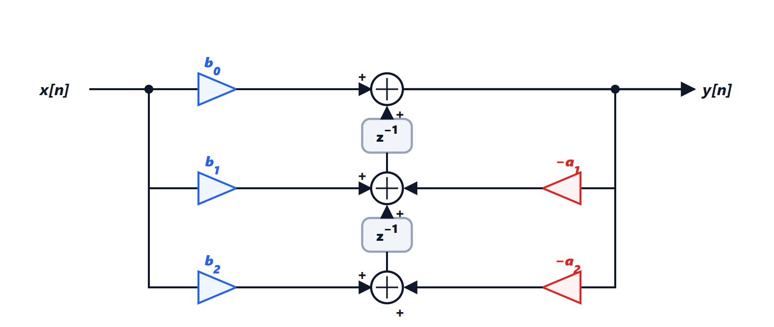
Direct form I implements it as it stands, with two delay lines, one for inputs and one for outputs. Direct form II swaps the order of the two parts (the system is linear, order does not matter) and shares a single delay line: it uses the minimum number of memory cells,  . The transposed form is obtained by reversing the direction of all branches and swapping input and output: it has the same transfer function and better numerical behaviour, because the additions happen right after the multiplications.
Why second-order sections are used
A high-order IIR filter implemented in direct form, with a single polynomial in the denominator, is dangerous: small errors in the coefficients move the poles a lot.
Theorem. Let  with distinct poles. The sensitivity of pole
 to coefficient
 is
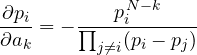
Proof. Write the denominator as a polynomial in  :
 , with roots
 . For every pole
 . Differentiating with respect to , taking into account that depends on :
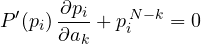
because  . Finally
 gives
 . ∎
The denominator is the product of the distances between the pole and all the others: if the poles are close together, as happens in selective filters, where they crowd near the unit circle around the passband, the sensitivity blows up. A rounding error on the coefficients can move a pole outside the circle and make the filter unstable. That is why an IIR filter is factored into a cascade of second-order sections (biquads), each with a single pair of poles: sensitivities stay small, each section can be checked on its own, and the order of the sections and the distribution of gain are chosen to reduce noise.
Fixed point
In inexpensive DSPs and in dedicated hardware numbers are in fixed point: for instance in Q15 format a 16-bit integer represents a value between  and
 . There are two problems:
- overflow: a sum exceeding 1 wraps around to , with an enormous error. It is prevented by scaling the signal at the input of each section, so that internal nodes do not exceed full scale, and the damage is limited by saturation arithmetic, which clamps the result at the maximum instead of letting it wrap;
- quantisation: every product has twice the bits and must be rounded, introducing a small error at every step. DSPs accumulate sums in longer registers (40 bits or more) and round only once at the end.
Round-off noise
The rounding error with step  is modelled as white noise uniform between
 and
 , with power
 (Signal Theory lesson on quantisation). But this noise does not leave the filter as it is: it goes through the part of the filter between the point where it arises and the output.
Theorem. White noise of power  entering a system with impulse response
 produces at the output noise of power
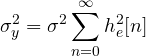
Proof. The output is  . Its power is
 . For white noise
 if
 and 0 otherwise, so only the sum of the terms with remains. ∎
Example. A first-order section  , with rounding at the summing node: the noise sees the whole filter,
 , and
 . With
 , a pole close to the circle, the factor is about 50, i.e. 17 dB more noise than a single rounding: almost 3 bits lost. This is why very selective low-frequency filters, with poles near
 , need more bits.
Limit cycles
In fixed-point IIR filters it can happen that, with zero input, the output does not go to zero but stays stuck at a constant value or a small oscillation: a limit cycle. Rounding causes it, by making the system non-linear: for instance with  , starting from 4 one gets
 , and the output stays at 4 forever instead of decaying. Limit cycles are avoided by rounding towards zero (magnitude truncation) or with special structures; in audio filters they are heard as faint tones in silence. FIR filters have no feedback, so they have neither limit cycles nor stability problems: another reason to choose them when precision is scarce.
DSP architecture
Signal processors are built around the operation  : a multiply-accumulate unit (MAC) that performs a product and a sum in one cycle, separate memories for data and coefficients read in parallel, circular buffers handled in hardware for delay lines and zero-overhead loops. An
 -tap FIR filter thus costs about cycles per sample. Today the same principles are found in the SIMD instructions of general-purpose processors and in the DSP blocks of FPGAs.