Laboratory Test and Electrical Measurements Report
Introduction The laboratory experience gave us a deeper understanding of electrical measurements on circuits and of the related evaluations. As theorised earlier, the result of a…
https://www.electronics-engineering.com/en/laboratory-test-and-electrical-measurements-report/
Introduction
The laboratory experience gave us a deeper understanding of electrical measurements on circuits and of the related evaluations. As theorised earlier, the result of a measurement does not coincide exactly with the true value of the quantity concerned, but is affected by a series of errors, which fall within an interval defined by the uncertainty. Therefore every measurement result must be accompanied by the value of the corresponding uncertainty. The determination of this uncertainty is based on mathematical functions studied in theory and varies with the type of measurement, direct or indirect. In direct measurements the uncertainty can be calculated using the specifications provided by the manufacturer of the instruments, while in indirect measurements it can be calculated using mathematical formulas that involve the uncertainties of the direct measurements on which they depend.
In the experiments carried out in the laboratory we used a series of instruments, including the HP54600B digital oscilloscope, the HP974A digital multimeter, the Wavetek FG3A waveform generator, 10X compensated probes, alligator-clip leads and a breadboard on which the circuit to be analysed was built. To determine the uncertainty of the measurements we referred to the specifications given in the manuals of the instruments used. We also calculated the uncertainty values using specifications from manuals other than those of the instruments used, in order to compare the instruments with one another and to learn how to interpret specifications, which can vary from manual to manual.
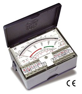
The instruments analysed in the measurements include the HP974A digital multimeter, the Fluke 8060A multimeter, the Norma D1216 multimeter, the HP 54501A digital oscilloscope, the HP 54600B digital oscilloscope, the NB-A2000 acquisition card and the LAB-PC+ acquisition card.
Structure of the report
The report is divided into three parts. The first part is based on laboratory test B, the second part is based on test C and the third part focuses on test D.
In the first part, the following aspects will be discussed:
- Use of the multimeter for continuity detection, diode testing and the measurement of precise resistances.
- Use of the oscilloscope with two traces in normal and XY mode.
- Characterisation of bipolar transistors (BJT): manual measurements in XY mode.
- Characterisation of bipolar transistors (BJT): automatic measurements in normal mode.
The measurement results and the calculations performed are presented in tables, obtained with Excel, a spreadsheet that lets you automate calculations through predefined or custom functions. In addition, functions describing the behaviour of each instrument were defined, and the code (written in VBA) associated with each table shows how these functions were determined. For a better understanding, you can consult the Excel files attached to the report.
Use of the multimeter as a continuity detector
With the continuity test we classified the waveform generator and the oscilloscope in terms of grounding. This test revealed that both instruments are single-ended, since continuity was detected between the outer shells of the oscilloscope BNC inputs and between the outer shells of the signal generator BNC outputs. In addition, both the signal generator and the oscilloscope are connected to ground, with continuity respectively between the outer shells of the generator outputs and the earth conductor, and between the outer shells of the oscilloscope inputs and the earth conductor.
After this analysis, it is essential to show the schematic diagram of the circuit on the breadboard.

List of components:
- R1: 100 ohm resistor, 5% tolerance, rated power 1/4 watt.
- R2: 120 ohm resistor, 5% tolerance, rated power 1/4 watt.
- R3: 470 ohm logarithmic potentiometer, rated power 1/4 watt.
- R4: 10,000 ohm (10 kilo-ohm) logarithmic potentiometer, rated power 1/4 watt.
- TR: Isolation transformer.
- E: Battery.
- BJT: Transistor under test (BC107).
The continuity test was used to check the efficiency of the transformer. This analysis confirmed that there is adequate decoupling between the primary and the secondary of the transformer. An isolation transformer was used because the ground potential of the oscilloscope does not coincide with that of the circuit. The transformer therefore decouples the circuit from ground, preventing potential differences from causing problems or damaging the equipment.





Benvenuti nella pagina su «Prova di Laboratorio e Relazione di Misure Elettriche». L'ho scritta pensando a chi studia ingegneria elettronica: se un passaggio non vi torna, un esercizio vi dà un risultato diverso o volete altro materiale sull'argomento, chiedete pure nei commenti e vi risponderò. Un voto con le stelle qui sopra mi aiuta a capire quali pagine migliorare.