S-parameters, reflection coefficient and the network analyser
Incident and reflected waves, return loss, SWR and mismatch with an example, the S matrix, power conservation in lossless circuits proved, measurement with the VNA.
At radio frequencies voltages and currents depend on the point of the line where they are measured, and the open and short circuits needed to measure the classic parameters of a two-port are impossible to realise or make transistors oscillate. A circuit is then described by the waves entering and leaving its ports: these are the scattering parameters, or S-parameters. In this lesson we look at incident and reflected waves, the reflection coefficient with the quantities derived from it and an example, the S matrix and the proof of the conservation relation for lossless circuits, and measurement with the network analyser.
Incident and reflected waves
On a transmission line with characteristic impedance  (usually 50 Ω) the voltage at every point is the sum of a wave travelling towards the load and one coming back (Electromagnetic Fields lesson on transmission lines). At the port of a circuit the incident wave
 and the reflected wave
 are defined, normalised so that
 and
 are the powers entering and leaving.
If the port is terminated on a load  , the reflection coefficient is
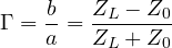
It is 0 for a matched load ( ),
 for a short circuit,
 for an open circuit. From
 derive the quantities used in practice:
- return loss:
 , how much weaker the reflected wave is;
- standing wave ratio:
 (lesson on standing waves);
- mismatch loss:
 , the power that does not enter the load.
Example. An antenna with  : return loss 20 dB, SWR 1.22, mismatch loss
 dB. 99 % of the power enters the antenna. With
 (SWR 2), 89 % still enters: a moderate mismatch costs little power, but it can damage a power amplifier or make it unstable.
The S matrix
For a two-port the outgoing waves depend linearly on the incoming ones:
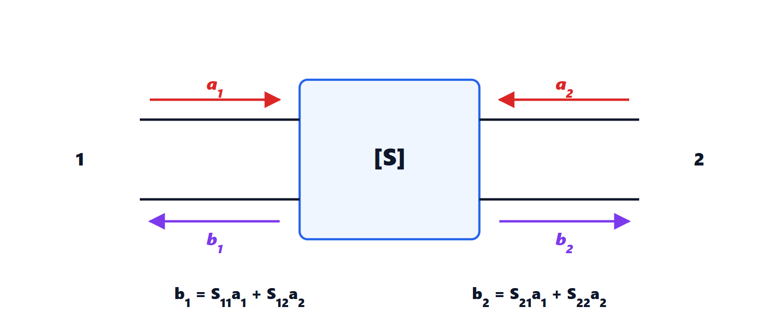
Each parameter is measured by terminating the other port in , i.e. with zero incoming wave:
 : input reflection coefficient with the output matched;
 : forward transmission gain (or attenuation);
 is the power gain between a 50 Ω source and load, and
 is the insertion loss of a filter or a cable;
 : reverse transmission, the isolation; for an amplifier it is small;
 : output reflection coefficient.
Terminating a port in 50 Ω is easy even at tens of gigahertz, and a transistor terminated in 50 Ω usually does not oscillate: this is why manufacturers supply radio-frequency transistors with tables of S-parameters versus frequency.
Lossless circuits
Theorem. In a lossless two-port  (and likewise
 ).
Proof. Port 1 is driven with a wave  and port 2 is terminated in a matched load, so
 . Power
 enters;
 leaves, reflected at port 1, and
 , transmitted to port 2. Without losses power is conserved:
 , and dividing by gives the result. ∎
More generally the S matrix of a lossless circuit is unitary, and that of a reciprocal circuit (without magnetised materials or active components) is symmetric,  . The theorem has a practical consequence: in a lossless filter, the power that does not pass is reflected. A filter with 20 dB return loss in the passband (
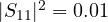 ) transmits 99 % of the power, i.e. it has an insertion loss of 0.044 dB due to mismatch alone. Out of band, where
 is small,
 is almost 1: the filter sends the signal back to the source.
Measurement
S-parameters are measured with the vector network analyser (VNA): it generates a swept-frequency signal and, with directional couplers, separates and measures in amplitude and phase the incident and reflected waves at each port. Before measuring, a calibration is performed with known standards (short, open, matched load, through connection), which allows the errors of cables and connectors to be corrected mathematically and the reference plane to be moved exactly to the device ports.
S-parameters describe linear behaviour; non-linear behaviour (compression, intermodulation) requires other measurements (lesson on non-linearity). The following lessons use S-parameters to design matching and amplifiers.




