Polarisation, reflection at normal incidence and standing waves
Linear, circular and elliptical polarisation, reflection and transmission coefficients with proof, anti-reflection coatings, standing waves and the standing wave ratio.
When a wave meets a different material, part of the energy is reflected and part continues. How much is reflected depends on the “jump” in wave impedance between the two materials, exactly as a voltage is reflected at the end of a cable connected to the wrong load. In this lesson we cover wave polarisation, reflection at normal incidence, standing waves and the standing wave ratio.
Polarisation
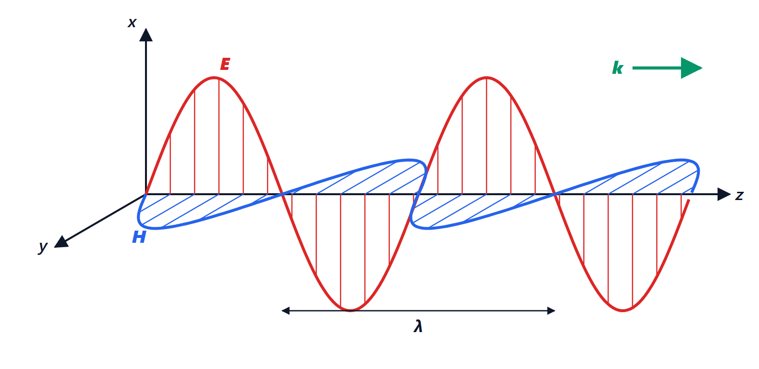
Polarisation describes how the tip of the electric field vector moves over time, in a plane perpendicular to the direction of propagation. In general the field has two components,  and
 :
- linear:
 or 180°: the tip swings along a segment. FM radio and Wi-Fi antennas are usually linearly polarised, vertical or horizontal;
- circular:
 and
 : the tip traces a circle, one way or the other (right- or left-handed). GPS satellites use it, because it is unaffected by the receiver’s rotation;
- elliptical: the general case.
An antenna receives well only the polarisation it is built for: a vertical antenna does not receive a horizontally polarised wave. That is why two nearby channels can use the same frequency with orthogonal polarisations, doubling capacity (done in radio links and TV satellites).
Reflection at normal incidence
A plane wave travels in material 1 (impedance  ) and hits the surface of material 2 (impedance
 ) perpendicularly, at
 . In material 1 there are the incident and the reflected waves, in material 2 the transmitted wave:

Theorem. The reflection and transmission coefficients are

Proof. The fields are tangential to the surface, so by the boundary conditions  and
 are continuous at . For the electric field:
 . For the magnetic field, recall that
 for the wave going towards
 and
 for the one coming back (the direction of
 reverses):
 . Substituting
 and solving gives
 . ∎
The reflected and transmitted powers are the fractions  and
 of the incident power (for lossless materials).
Examples.
- Air and glass (
 , so
 ):
 , 4% of the light is reflected at each surface. The anti-reflection coatings on glasses and lenses are films a quarter wavelength thick (about 100 nm for green light) that make the two reflections interfere destructively.
- Perfect conductor (
 ):
 , total reflection with phase inversion. It is the principle of radar and metal mirrors.
Standing waves
With the total wave in material 1 is

It no longer travels: it is a standing wave, with amplitude  that vanishes at the nodes (every
 , the first on the conductor’s surface) and is largest at the antinodes. In a microwave oven, at 2.45 GHz,
 cm and the nodes are about 6 cm apart: that is why the plate turns, otherwise food would stay cold in patches.
With partial reflection the wave is partly standing and partly travelling: the amplitude swings between a maximum and a minimum.
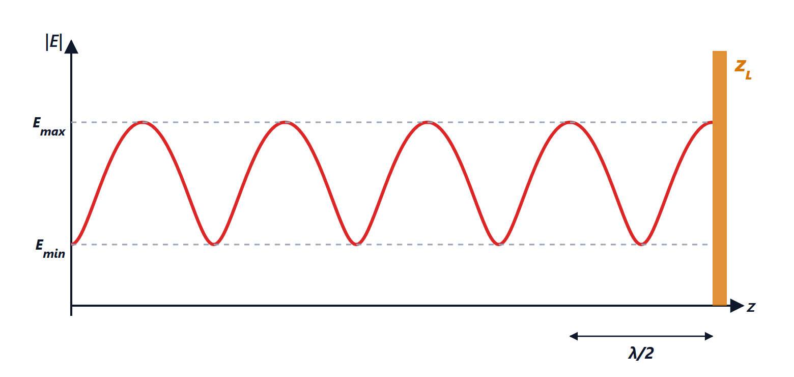
Maximum and minimum occur where the two waves are in phase and in antiphase:

Their ratio is the voltage standing wave ratio (VSWR):
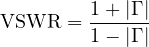
It is 1 with no reflection and tends to infinity with total reflection. It is easily measured by moving a probe along the line, and it is the parameter used to check, for example, that an antenna is properly connected to the transmitter: a VSWR of 2 corresponds to  , that is 11% of the power reflected. The same concept, with voltages instead of fields, applies to transmission lines, where reflection arises from a load different from the characteristic impedance.