The NE555 Timer: How It Works, Pinout and Typical Circuits
What is inside the 555, what the eight pins are for and how to calculate the monostable and the astable, with numerical examples and practical tips.
https://www.electronics-engineering.com/en/the-ne555-timer-how-it-works-pinout-and-typical-circuits/
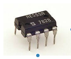
The NE555 is probably the longest-lived integrated circuit in electronics: designed by Hans R. Camenzind in 1970 and put on the market by Signetics in 1971, it is still made today in enormous quantities. The reason is simple: with two resistors and a capacitor you get a stable, cheap and easy-to-calculate timer or oscillator.
On this page we look at what is inside it, what the eight pins are for and how to size the two most widely used circuits, the monostable and the astable.
What is inside
The heart of the 555 is a divider made of three equal 5 kΩ resistors (it is often said that the name comes from this, although Camenzind himself said that the number was chosen by Signetics) that sets two reference voltages: 1/3 and 2/3 of the supply voltage. Around the divider there are:
- two comparators: one compares the TRIGGER pin with 1/3 of VCC, the other compares the THRESHOLD pin with 2/3 of VCC;
- an SR flip-flop, driven by the two comparators, that decides the state of the output;
- a discharge transistor connected to the DISCHARGE pin, which conducts when the output is low and serves to empty the timing capacitor;
- an output stage able to source or sink up to about 200 mA in the bipolar version.
In all, the bipolar version contains about twenty transistors, a few diodes and about fifteen resistors, normally packaged in an 8-pin DIP or in an SMD version (SO-8).
The pinout
| Pin | Name | Function |
|---|---|---|
| 1 | GND | Ground |
| 2 | TRIGGER | When it falls below 1/3 of VCC it drives the output high and starts the cycle |
| 3 | OUTPUT | Output |
| 4 | RESET | Active low: if pulled to ground it resets everything. If not needed it must be connected to VCC |
| 5 | CONTROL | Direct access to the 2/3 reference: usually connected to ground through a 10 nF capacitor |
| 6 | THRESHOLD | When it exceeds 2/3 of VCC it drives the output low |
| 7 | DISCHARGE | Open collector of the discharge transistor |
| 8 | VCC | Supply: 4.5–16 V for the bipolar NE555 |
The monostable: a pulse of fixed duration
In monostable operation the 555 rests with the output low. A short negative pulse on the TRIGGER drives the output high and turns off the discharge transistor: capacitor C starts charging through resistor R. When the voltage on C reaches 2/3 of VCC, the threshold comparator resets the flip-flop, the output goes low again and the capacitor is discharged. The duration of the pulse is:
T = 1.1 · R · C
The factor 1.1 comes from ln(3) ≈ 1.0986, because the capacitor charges from 0 to 2/3 of the final voltage. With R = 100 kΩ and C = 10 µF you get a pulse of about 1.1 seconds. The nice thing about this formula is that it does not depend on the supply voltage: the accuracy depends almost only on the tolerance of R and C, so for long times it is better to use film or tantalum capacitors instead of electrolytic ones, which have large tolerances and leakage currents.
The astable: a square-wave oscillator
In the astable, pins 2 and 6 are connected together to the capacitor, and between VCC, pin 7 and the capacitor there are two resistors, R1 and R2. The capacitor charges through R1 + R2 up to 2/3 of VCC, then discharges through R2 (and pin 7) down to 1/3 of VCC, and the cycle restarts by itself. The times are:
- output high: tH = 0.693 · (R1 + R2) · C
- output low: tL = 0.693 · R2 · C
- frequency: f = 1.44 / ((R1 + 2·R2) · C)
An example: R1 = 1 kΩ, R2 = 10 kΩ, C = 100 nF give tH ≈ 0.76 ms, tL ≈ 0.69 ms and a frequency of about 686 Hz, that is a nearly square wave (52% duty cycle).
With this circuit the duty cycle is always greater than 50%, because charging goes through both resistors and discharging only through R2. If you need a symmetrical wave or a lower duty cycle, add a diode in parallel with R2 (anode towards pin 7): when charging the current passes only through R1 and the diode, when discharging only through R2, and the two times can be adjusted independently.
The bistable
Without the timing resistor and capacitor the 555 becomes a simple flip-flop: a low pulse on the TRIGGER drives the output high, a low pulse on the RESET brings it low again (with THRESHOLD connected to ground). It is the cheapest way to remember the state of a button, for example to switch a load on and off with two keys.
Variants and practical tips
- NE556: two 555s in the same 14-pin package. NE558: four timers with some differences in operation.
- CMOS versions (TLC555, ICM7555, LMC555): they work from 2–3 V, draw a few microamperes at rest and disturb the supply much less, but deliver less output current. For battery circuits they are almost always the right choice.
- The bipolar 555 draws a current spike at every switching: a 100 nF capacitor near pin 8, plus an electrolytic of a few microfarads, prevents disturbances on the rest of the circuit.
- If pin 5 is not used, a 10 nF capacitor to ground makes the thresholds much more stable.
- For an inductive load (relays, small motors) you always need a diode in antiparallel across the coil.
Monostable, astable and bistable are the basis of a great many circuits: flashers, tone generators, power-on delays, PWM modulators, missing-pulse detectors. A collection of application circuits can be found on the page linked below.





Sono l'autore di questa pagina su «Il timer NE555: come funziona, piedinatura e circuiti tipici». Se qualcosa non è chiaro, se vi serve un esempio in più o volete approfondire un punto, scrivetelo qui sotto nei commenti: rispondo personalmente. Se la pagina vi è stata utile, lasciate un voto con le stelle in cima all'articolo.