Heat conduction: Fourier's law and thermal resistance
Fourier's law and material conductivities, the plane wall with proof, thermal resistance, the composite wall and transmittance with an example, the cylinder, critical radius, contact resistance.
Thermodynamics says how much heat is exchanged, heat transfer says how fast. There are three mechanisms: conduction, convection and radiation. In this lesson we study conduction, the passage of heat through a stationary material, introduce thermal resistance, which makes thermal problems similar to electric circuits, and apply it to walls, pipes and insulation.
Fourier’s law
The heat flux per unit area is proportional to the temperature gradient and flows from hot to cold:

where  is the thermal conductivity, in W/(m·K). Its values vary widely:
| Material | in W/(m·K) |
|---|---|
| copper | 400 |
| aluminium | 237 |
| steel | 15-50 |
| glass | 1 |
| brick | 0.5-0.9 |
| water | 0.6 |
| rock wool, polystyrene | 0.03-0.04 |
| still air | 0.026 |
Insulators work by trapping still air in small cells, because air conducts very little as long as it does not move.
The plane wall
Theorem. In a plane wall of thickness  , area
 and constant conductivity , in steady state, temperature varies linearly between the two faces and the heat crossing it is

Proof. In steady state and with no internal generation, the heat entering each thin layer equals the heat leaving it, so the flux  is the same at every depth
 . By Fourier’s law
 is constant: temperature is linear, and integrating from 0 to gives
 . Multiplying by the area gives the statement. ∎
The formula is the thermal Ohm’s law: the temperature difference is the “voltage”, the heat flow the “current”,  the thermal resistance in K/W. All the circuit rules follow: resistances of layers in series add up, those of parallel paths combine like conductances.
The composite wall
A house wall is made of different layers, and on each face there is convective exchange with the air, described by a resistance  (next lesson).
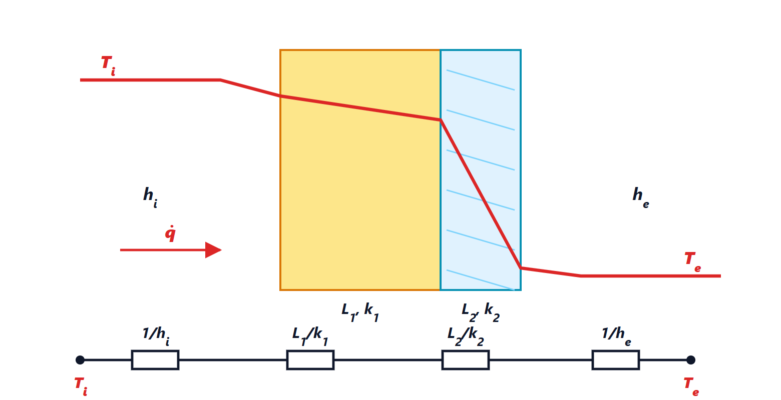
Per square metre of wall:

 is the thermal transmittance, in W/(m²·K), the figure limited by building energy-efficiency regulations.
Example. A 25 cm brick wall ( ), coefficients
 and
 W/(m²·K):
 m²·K/W,
 W/(m²·K). Adding 8 cm of insulation (
 ,
 ):
 ,
 W/(m²·K). The heat lost falls more than fivefold: with a 20 °C difference, from 38 to 7 W per square metre. It also shows in the temperature profile: almost the whole drop happens in the insulation, the largest resistance in the series.
The cylinder and pipe insulation
For a cylindrical layer (a pipe or its lagging) between radii  and
 , of length :
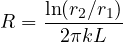
Proof. In steady state the same heat  crosses every cylindrical surface of radius
 , of area
 :
 . Separating variables,
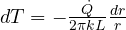 , and integrating from to :
 . ∎
The logarithmic dependence has a curious consequence: adding insulation increases the conduction resistance, but it also increases the outer surface exchanging by convection. For very thin pipes and cables, below a critical radius  (about 1 cm for a plastic insulator in still air), a thin coating makes them lose more heat rather than less. For electrical wires this is an advantage: the sheath helps cool them.
Contact resistance and internal generation
Two solid surfaces in contact never touch perfectly: air remains between the asperities, creating a contact resistance. In electronics it matters a great deal: between a component and its heat sink a thermal paste or thermal pad is placed, filling the gaps and cutting this resistance by up to ten times.
When heat is generated inside the material (a resistor carrying current, a winding, a chip) the temperature profile is no longer linear but parabolic, with its maximum where heat finds it hardest to get out. That is why the hottest point of a component, the junction, is inside it and cannot be measured directly: it is computed with thermal resistances, as we will see in the next lesson.